Table of Contents
Advertisement
Quick Links
Advertisement
Table of Contents

Related Manuals for BMZ Hyperion 15


Summary of Contents for BMZ Hyperion 15
- Page 1 Hyperion Lithium Ion Energy Storage ORIGINAL INSTALLATION INSTRUCTIONS...
- Page 2 Zeche Gustav 1 63791 Karlstein am Main Germany Tel.: +49 6188 9956-0 Fax: +49 6188 9956-900 E-mail: mail@bmz-group.com Hyperion BMZ item no. 41871 Product identification Helios Battery Module item no. 37832-02 Model: Hyperion Lithium Ion Energy Storage Country of Origin: Germany...
-
Page 3: Table Of Contents
Table of Contents Table of Contents Safety Important notes on this manual 1.1.1 Purpose 1.1.2 Target group 1.1.3 Storage Symbol explanations 1.2.1 Explanations regarding safety instructions and warnings 1.2.2 Explanation of pictograms and symbols Battery application area 1.3.1 Appropriate use 1.3.2 Perilous misuse Main hazards... - Page 4 3.3.1 Installing Helios modular batteries 3.3.2 Connect Helios modular batteries next to each other in series 3.3.3 Closing the housing of the battery system 3.3.4 Adding battery modules 3.3.5 Disposal Connecting the inverter 3.4.1 SMA Sunny Boy Storage 3.7 / 5.0 / 6.0 3.4.2 Kostal PLENTICORE plus Putting the Hyperion storage system into operation...
-
Page 5: Safety
Important notes on this manual 1.1.1 Purpose This document describes the installation of a BMZ Hyperion battery system in combination with SMA Sunny Boy Storage 3.7/5.0/6.0 or Kostal PLENTICORE plus. 1.1.2 Target group The installation instructions are intended exclusively for qualified electricians. -
Page 6: Explanation Of Pictograms And Symbols
1 Safety Warnings are placed directly before the instructions of the respective action. They Warnings help you to avoid dangers during the upcoming action. They consist of the following elements: Table 1: Warnings Warning indicates all hazards with regard to death or injury along with a signal word. triangle Signal word DANGER... -
Page 7: Battery Application Area
In a battery system, 3 to 6 Helios modular batteries can be connected to one another in series. BMZ GmbH is not liable for personal injury and/or material damage due to improper use of the energy storage system. The battery system is a self-contained unit which is only functional after proper Limits installation with an approved inverter. -
Page 8: Perilous Misuse
Qualification of the users Only the electricians qualified by BMZ GmbH or BMZ GmbH itself may install the battery system. Page 8 of 28... -
Page 9: Personal Protective Equipment (Ppe)
1 Safety Do not leave the children unattended or allow them to be near the battery system. Children People with High currents have effects on medical implants. implants People with implants must be careful not to be in the direct vicinity of the battery during operation. -
Page 10: Product Description
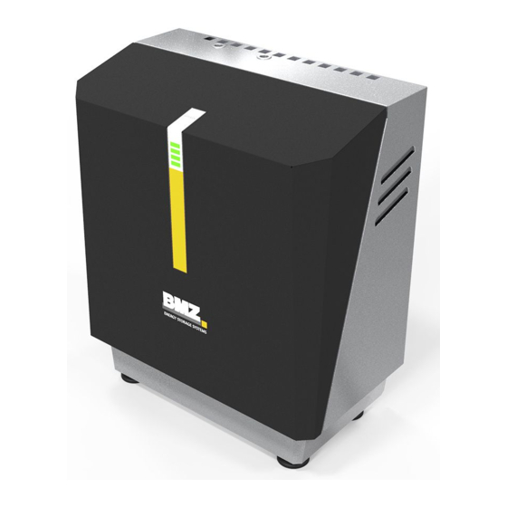
2 Product description Product description Important information about the product 2.1.1 Overall view Implementation Figure 1: Overall view of for communication battery system Implementation for power cables Status display DC disconnectors SOC display detachable hood adjustable base 2.1.2 Conformity The following standards, laws and guidelines were taken into account during the development of the modular battery: ... -
Page 11: Scope Of Delivery
2 Product description Scope of delivery Hyperion system housing Installation kit (in system housing) is included: 7 RJ45 patch cables 12 screws M6x10 3 Dummy sockets, power plugs 2 PG connections ▪ 1 Three-hole cable bushing ▪... -
Page 12: Compatible Inverters
2 Product description 2.3.3 Compatible inverters SMA Sunny Boy Storage 3.7 / 5.0 / 6.0 (CAN) COSTAL PLENTICORE plus (RS-485) 2.3.4 Supply, interfaces, connections Battery system The battery system is supplied with the following connections: + DC cable: AWG8 red (American standard for wire cross section) ... -
Page 13: Status And Soc Display
3 Commissioning Status and SOC display During operation 6 LED fields indicate status and SOC of the battery system. 10 seconds Table 4: Overview LED Status status codes Green – on Discharge mode Green - flashes Ready (battery relay engaged - waiting for (0,5 s on / 1 s off) charge or discharge) Green –... -
Page 14: Choice Of Installation Site
3 Commissioning The modular batteries should be transported to the installation site in their original Modular batteries packaging. 3.2.2 Choice of installation site The battery system can be mounted upright on the floor or in a hanging position on the wall. Recommendation It is recommended that the battery system be installed on the floor against a wall, where the inverter can be mounted centrally above it. -
Page 15: Assembly
3 Commissioning Assembly 3.3.1 Installing Helios modular batteries CAUTION Safety Instructions Risk of crushing due to improper installation. Falling or improper insertion of the module can cause slight bruising and abrasions to hands and feet. Wear protective clothing. CAUTION Ergonomic hazards due to heavy lifting. - Page 16 3 Commissioning Make sure that the DC disconnector of the Hyperion is set to "off". Instructions Loosen the two screws and I, with which the downholder is fixed on the left and right, and lift up the downholder. Unpack and insert the modular batteries. NOTICE: To ensure the best possible cooling;...
-
Page 17: Connect Helios Modular Batteries Next To Each Other In Series
3 Commissioning Figure 4: Modular batteries fixed to the grounding support Use the patch cables to connect the BMS master (left of the two RJ45 sockets) with the installed modular batteries. For example, refer to Figure Figure 5: Connecting the modules to the BMS master with patch cables Connect the last module with the master’s left RJ45 socket (RJ45-B). -
Page 18: Closing The Housing Of The Battery System
3 Commissioning Figure 6: Power path with switching devices and BMS Check by pulling the power plugs to make sure that the latching is engaged. If there are less than 6 modular batteries: fit the power plugs not required with the dummy sockets C supplied. Feed the power cables (red and black) as well as PE (yellow-green) through the left hole in the basic housing and fix them with the supplied PG screw connection. -
Page 19: Adding Battery Modules
Figure 7: Connecting the SMA SB Storage to the BMZ Hyperion Connect the cables in the inverter according to the Sunny Boy Storage 3.7 / 5.0 / 6.0 operating instructions. V1.2 | 06/08/2020 Page 19 of 28... -
Page 20: Kostal Plenticore Plus
Plug X2 back into BMS master. Preparation: Ground the Hyperion housing: PE ▪ Yellow-green Connect to grounding rail Figure 8: Connecting the PLENTICORE plus to the BMZ Hyperion Page 20 of 28 Original installation instructions Hyperion Lithium Ion Energy Storage... - Page 21 3 Commissioning Feed the communication cable through the respective PG screw connections into the connection compartment of the inverter. Connect the cables in/on the inverter according to the PLENTICORE plus operating instructions. Connecting battery communication cable: ▪ white: RS485B ▪...
-
Page 22: Putting The Hyperion Storage System Into Operation
4 Repair Putting the Hyperion storage system into operation Instructions Switch the DC disconnector on the left side of the Hyperion to "on". Commission the storage system according to the operating manual of the connected inverter. Repair The modular battery may only be opened and repaired by the manufacturer. Defective modules will be sent to the manufacturer's service department. -
Page 23: Cleaning
6 Packing and transport The following conditions should prevail on an average: Temperature: 15 … 25 °C Tough limits: Storage: -10 … 50 °C Transport: -20 … 60 °C Relative humidity: 0 … 50 % No more than 4 modular batteries may be stacked on top of each other. Store modular batteries at least 15 cm above the floor to reduce the risk of water damage. -
Page 24: Appendix
8 Appendix Appendix BMS master, DC-DC converter and relay in the Hyperion Figure 9: Position of BMS master, DC-DC converter, relay and precharge resistor BMS master DC-DC converter X4 RJ45-B RJ45-A Assignment BMS master inverter interface (X2) Table 5: Pin assignment Hyperion SMA Sunny Boy Storage 3.7 / Kostal PLENTICORE plus... -
Page 25: Adjusting System Voltage With Sma Sb Storage
8 Appendix Adjusting system voltage with SMA SB Storage To add Helios battery modules, the system voltage must be adjusted to the module voltage. For this purpose set the Sunny Boy Storage to a specific SOC: Open the Sunny Boy Storage user interface. Register as installer. -
Page 26: Further Directories
Figure 5: Connecting the modules to the BMS master with patch cables ..... 17 Figure 6: Power path with switching devices and BMS .......... 18 Figure 7: Connecting the SMA SB Storage to the BMZ Hyperion ......19 Figure 8: Connecting the PLENTICORE plus to the BMZ Hyperion ......20... - Page 28 Batterien-Montage-Zentrum GmbH Zeche Gustav 1 63791 Karlstein am Main Germany Tel.: +49 6188 9956-0 Fax: +49 6188 9956-900 E-Mail: mail@bmz-group.com Page 28 of 28 Original installation instructions Hyperion Lithium Ion Energy Storage...
Need help?
Do you have a question about the Hyperion 15 and is the answer not in the manual?
Questions and answers