Table of Contents
Advertisement
Quick Links
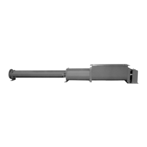
Progressing cavity pump
Operating and maintenance instructions Series AE.N
with instructions for assembly and
disassembly
Retain the operating instructions for future use!
This is a translation of the original operating instruction.
Refer to the order-specific section of the documentation for operational data, dimensions and other additional
information.
Order No.:
Machine No.:
Edition
BA-2011.04
Print No.
151 999
VM-No.
760.0003 GB
Subject to technical changes!
Important note:
These operating instructions are supplemented with order-specific information.
Construction Type RG
Pump ID No.:
Pump model:
ALLWEILER AG – Bottrop plant
P.O. Box 200123 · 46223 Bottrop
Kirchhellener Ring 77-79 · 46244 Bottrop
Germany
Telephone: +49 (0) 2045-966-60
Fax:
+49 (0) 2045 966-679
E-mail:
service@allweiler.de
Internet:
www.allweiler.com
Advertisement
Table of Contents

Related Manuals for Colfax Allweiler AE Series


Summary of Contents for Colfax Allweiler AE Series
- Page 1 Progressing cavity pump Operating and maintenance instructions Series AE.N with instructions for assembly and disassembly Construction Type RG Retain the operating instructions for future use! This is a translation of the original operating instruction. Refer to the order-specific section of the documentation for operational data, dimensions and other additional information.
- Page 2 These operating and maintenance instructions contain notices from the pump manufacturer. It may be necessary to amend these instructions with instructions from the company that operates the pump. Specific notices about operating and maintaining the overall system in which the pump is integrated are not provided here. These must be provided by the persons who are responsible for planning and constructing the system (system manufacturer).
-
Page 3: Table Of Contents
Table of contents Table of contents 1 About these instructions ......1 Performance data ......7 Design ......... 7 Who should read these 4.4.1 Structural design ......7 instructions ........1 4.4.2 Bearing and lubrication ....7 Related documents ...... 1 4.4.3 Shaft seal ........ - Page 4 Table of contents 6.7.2 Safety device in the pressure 10.2 Assembling the progressing line ..........15 cavity pump ....... 26 6.7.3 Electrical connections ....16 10.2.1 Installing the drive shaft and spur gears on pump sizes 100 7 Operation ..........17 …...
- Page 5 Table of Figures Listing of Tables Table of Figures Tab. 1 Who should read these instructions ..1 Fig. 1 Nameplate (example) ......7 Tab. 2 Other applicable documents ....1 Fig. 2 Model code ..........7 Tab. 3 Overview of dangers ......1 Fig.
- Page 6 Listing of Tables Series AE.N BA-2011.04 760.0003 GB - 151 999 Construction Type RG...
-
Page 7: About These Instructions
About these instructions Who should read these instructions unavoidable residual hazards during usage of About these instructions the machine. These residual hazards are These instructions: related to: • • are part of the pump, people • • are valid for the specified series and the machine construction types, •... -
Page 8: Technical Terms
About these instructions Technical terms 1.4 Technical terms 1.7 Inspection Pump: "Pump" refers to the pump without All pumps are subjected to leak and coupling, drive, or any other components. performance tests before leaving our factory. Only flawlessly operating pumps that meet our Pump unit: "Pump unit"... -
Page 9: Safety
Safety Dangers of failure to observe safety notices 2.3 Avoiding common mistakes Safety (examples) The operating instructions contain important • Always observe the pump’s operational notices that must be observed during set-up, limits regarding temperature, pressure, operation, and maintenance. For this reason, capacity, viscosity, and speed. -
Page 10: Personnel Responsibilities
Safety Safety precautions applicable standards and Before switching on the system, ensure that no directives of the country where the one will be endangered by starting of the pump is operated system. ► Provide access to personal protective The system must be regularly checked for equipment. -
Page 11: Unauthorized Conversion And Production Of Spare Parts
Safety Unauthorized conversion and production of spare parts When performing any maintenance, Wear safety glasses when working near the inspection, and repair tasks, always shut off shaft seal area. the power to the system and secure the switch against unintentional restarting. ►... -
Page 12: Danger Points
Danger points Hazards when working with the system connections and charred cables must be Danger points removed immediately. 3.1 Hazards when working with the Proper earthing must be provided whenever system there is the potential for electrostatic charges. The progressing cavity pump was built according to the current state of technology If it is necessary to work on live parts, always and recognized safety regulations. -
Page 13: Design And Function
Design and function Application and area of usage 4.3 Performance data Design and function Refer to the order data sheet for the exact performance data applicable to the pump. 4.1 Application and area of usage Progressing cavity pumps are self-priming, 4.4 Design rotating displacement pumps suitable for pumping and metering low-viscosity and high-... -
Page 14: Pump Unit Design
Design and function Pump unit design over the length of the pumping elements, these two points form an equal number of sealing lines along the length of the pumping elements. As the rotor turns, the contents located in the resulting sealed chambers are moved axially and continuously from the suction to the pressure side of the pump. -
Page 15: Transport, Storage, And Disposal
Transport, storage, and disposal Packaging 5.3 Preserving progressing cavity Transport, storage, and disposal pumps and placing them into storage 5.1 Packaging Observe the graphical symbols on the 5.3.1 Preserving packaging. The pump’s suction and pressure sides and Notice! auxiliary connections must be closed with Not necessary with stainless plugs during transport and storage. -
Page 16: Removing Preservative
Transport, storage, and disposal Preserving progressing cavity pumps and placing them into storage • Notice! Choose cleaning agents appropriate for the area of usage ( Cleaning agents, The elastomer stator in the page 11). progressing cavity pump is • particularly sensitive to the Dispose of preservatives according to local elements (ozone, light, regulations. -
Page 17: Cleaning Agent
Transport, storage, and disposal Disposal Reference to “Internal preservation” point from Tab. 5, page 10. Caution! Use of improper preservatives may damage the seal, universal joint collar, and stator elastomer. ► Ensure that the seals, universal joint collars, stator elastomers, and rotor screw are preserved with silicone oil only. -
Page 18: Installation And Connection
Installation and connection Setting up the pump Caution! Installation and connection If the base plate is supported only at isolated points, this will cause the 6.1 Setting up the pump pump unit to sag in the center or Pumps must be installed horizontally. warp. -
Page 19: Base Plate
Installation and connection Base plate Make sure that the entire length of 6.4 Coupling the base plate has support during Fine adjustment of the coupling: mortaring and packing of the mortar compound. Tap the base plate to detect any unfilled areas. Fill any Danger! unfilled areas that are found! Life-threatening danger from... -
Page 20: Assembling Pump And Drive
Installation and connection Assembling pump and drive • Lay the straightedge over both 6.5 Assembling pump and drive halves of the coupling. If the pump unit will be put together at the • If there is a light gap at the outer place of installation, establish the coupling diameter, align the drive using connection as follows:... -
Page 21: Laying The Pipes
Installation and connection Laying the pipes Provide enough room for maintenance and protrude inward. Blank flanges, plugs, repair tasks, especially for the replacement of protective film, and/or protective coatings on pumping elements. Disassembly dimensions flanges and sealing strips must be completely for the stator and rotor are provided in the removed. -
Page 22: Electrical Connections
Installation and connection Safety and inspection equipment 6.7.3 Electrical connections Caution! A professional electrician must attach the coupled drive motor’s power supply cable in accordance with the connection diagram provided by the motor manufacturer. All VDE regulations and regulations from the local power supply company must be obeyed. -
Page 23: Operation
Operation Preparing for initial start-up 7.2 Bringing the pump into Operation operation 7.1 Preparing for initial start-up 7.2.1 Starting 7.1.1 Filling the pump with liquid Caution! Open all blocking devices on the Caution! suction and pressure sides before The pump may not run dry! starting. -
Page 24: Measures For Longer Periods Of Downtime
Operation Special applications of the pump 7.3.2 Measures for longer periods of downtime If operations will be interrupted for a longer period of time and there is a danger of frost, the pump must be emptied. 7.4 Special applications of the pump If the progressing cavity pump will be used to transport food or if it will be used in the... -
Page 25: Maintenance Cycles And Intervals
Maintenance cycles and intervals Special applications of the pump Maintenance cycles and intervals Maintenance may be necessary for the following parts: Rotor + stator: Wear to the rotor and/or stator is manifested in the form of lower pump capacity and lower pressure. -
Page 26: Preventive Maintenance
Preventive Maintenance Preventive Maintenance Preventive Maintenance Oil volume Pump size cm³/ joint 9.1 Preventive Maintenance • Observe the information provided in section 2 Safety whenever performing maintenance and repair tasks. • Regular monitoring and maintenance of the pump and drive will extend the service life. -
Page 27: Shaft Seal
Preventive Maintenance Preventive Maintenance 9.1.5 Shaft seal Installing the packing rings Drive-side shaft seals are stuffing boxes; Caution! stator-side shaft seals are in the form of running-gear seals. Use only the packing rings specified in our pump parts lists. Refer to the pump parts list for the Danger! dimensions and required quantity of Functional inspection and/or... -
Page 28: Running Gear Seal
Preventive Maintenance Preventive Maintenance Caution! The temperature of the stuffing box may not increase abnormally during this time. Approximately 20 to 60 ° C above the temperature of the pumped liquid is permissible. If temperature increases suddenly, immediately loosen the stuffing box gland and repeat the run-in process. -
Page 29: Maintenance
Maintenance Disassembly and assembly instructions 2. Disconnect the motor’s power cord. 10 Maintenance Prevent the motor from switching on unexpectedly. 3. All blocking devices in the feed and 10.1 Disassembly and assembly pressure lines must be closed. instructions Trained customer service technicians are Be certain that the pump is available upon request for assembly and repair pressureless. -
Page 30: Fig. 7 Removing The Joint Clamp
Maintenance Disassembly and assembly instructions 4. Remove the seal for the suction case (303). Deflect the universal joint shaft (501). (307) to do this (see image below). 5. Use a metal saw to cut open the seal on the joint clamp (306); use a screwdriver to press it outward to both sides. -
Page 31: Removing The Universal Joint Shaft And The Drive-Side Joint
Maintenance Disassembly and assembly instructions 10.1.7 Removing the drive shaft and 10.1.4 Removing the universal joint spur gears on pump sizes 100 shaft and the drive-side joint … 2700 For the positions of referenced parts refer to Remove the drive shaft and spur gears after sectional drawings on pages 43 and 45. -
Page 32: Removing The Hollow Shaft And
Maintenance Assembling the progressing cavity pump 4. Pull out drive shaft (118) from the 17. Loosen circlip (22) and pull out of hollow shaft (90). groove. 18. Pull spur gear (14) and (27) out of the bearing bracket (110) together. 10.1.9 Removing the hollow shaft 19. -
Page 33: Fig. 10 Installation Position Of The Spur Gears
Maintenance Assembling the progressing cavity pump 2. Press the shaft seal ring (29) (112) into the clean seat of the bearing bracket (110). 3. On the stuffing box side, the shaft seal (29) (112) must close flush with the seat of the bearing bracket (110). Notice! The sealing lip with the shaft seal ring’s hose spring must always... -
Page 34: Installing The Hollow Shaft And Spur Gears On Pump Size 5000
Maintenance Assembling the progressing cavity pump Notice! Notice! The sealing lip with the shaft seal The sealing lip with the shaft seal ring’s hose spring must always ring’s hose spring must always face the side being sealed face the side being sealed (pointing inward). -
Page 35: Fig. 11 Installation Position Of The Spur Gears
Maintenance Assembling the progressing cavity pump (90). First lightly oil the hollow shaft and tapered rollers. Support the hollow 9. Slide spur gears (14) and (27) into shaft with a suitable tool. each other with opposing key grooves; 18. Lightly oil the threads of the bearing insert them into the bearing housing nut (116) and use a hook wrench to (110) with the collar pointing towards... -
Page 36: Fig. 12 Pressing In The Joint Bush
Maintenance Assembling the progressing cavity pump inside ring, re-loosen first the threaded 29. Use the hexagon screws (139) to pin that is closest to the location with fasten the bearing cover (131) to the the largest deviation. Then tighten the bearing bracket (110). -
Page 37: Tightening With Band-It Clamping Tool And Adapter J050
Maintenance Assembling the progressing cavity pump 5. Slide the joint pin (301) into the joint bush (302) and fully drive in bushes for joint pin (303). 6. Where needed, grind the outer diameter of the joint sleeve (304) and pull onto the head of the rotor (401). 7. -
Page 38: Tightening With Clamping Tool Pok- It Ii
Maintenance Assembling the progressing cavity pump Notice! Caution! The image below shows proper If the joint clamp is raised slightly tightening of the joint clamps (306). on the cut side, counteract this by carefully rebending it. Hammering or striking the joint clamp seal is not acceptable because this may cause damage to the collar! Notice! -
Page 39: Installing The Stuffing Box Casing
Maintenance Assembling the progressing cavity pump 4. Pull on joint collar (308), fill joint area Caution! with joint oil, and fasten joint clamps as First lightly oil the bore of the described. hollow shaft (90). Do not use lubricant that contains MoS2. 10.2.5 Installing the stuffing box casing 1. -
Page 40: Design And Functionality Of The Running Gear Seal
Maintenance Assembling the progressing cavity pump special effort to protect the finely machined Even after relatively short periods of running, gliding surfaces of the metallic parts and the sliding surfaces will wear into each other. If elastomer parts from damage and you attempt to reinstall these parts, it will not contamination. -
Page 41: Fig. 19 Installing Running Gear Seal
Maintenance Assembling the progressing cavity pump Correct Incorrect Incorrect 11. Drive the retainer (72) into the seal sleeve flush with the outside. 12. Pull on O-ring (80) (87). 13. Install running gear seal (79) with installation tool. Direct the force directly over the elastomer part (see next figure). -
Page 42: Installing The Shaft Seal
Maintenance Assembling the progressing cavity pump 18. Slide running gear cartridge onto the shank of the worm shaft (50). To facilitate installation, surfaces over which O-rings glide may be lubricated with silicon oil, polydiol, or lubricating soap, for example. Caution! Do not use regular oil. - Page 43 Maintenance Assembling the progressing cavity pump 4. If bracket (612) is present, slide it onto the clamp bolts (611). 5. Use the clamp bolts (611) and hexagon nuts (609) to screw into place the pressure casing (504), bracket (612) if present, stator (402), and stuffing housing (40).
-
Page 44: Spare Parts
Spare parts 11 Spare parts The following sectional drawings show all referenced pumps. Index of parts also included. The parts labeled in the index of parts can be used as spare/reserve parts. Caution! For safety reasons, stock and use only original spare parts provided by Allweiler. -
Page 45: Index Of Spare Parts And Recommended Spare/Reserve Parts
Spare parts Index of spare parts and recommended spare/reserve parts 11.1 Index of spare parts and recommended spare/reserve parts Legend for recommended spare parts: R = large repair kit r = small repair kit Not applicable to AE.N 5000 8 units for AE.N 5000 12 units for AE.N 5000 16 units for AE.N 5000 24 units for AE.N 5000... - Page 46 Spare parts Index of spare parts and recommended spare/reserve parts Part No. Description Repair kit Quantity Remarks Spring ring Stuffing housing Stud bolt Hexagon nut Spring ring Washer Screw sealing material Centering pin Worm shaft Oil sight glass Seal Supporting washer O-ring Hexagon screw Spring ring...
- Page 47 Spare parts Index of spare parts and recommended spare/reserve parts Part No. Description Repair kit Quantity Remarks Screw lock Radial ball bearing Thrust bearing Hexagon screw Spring ring Bearing cover seal Bearing bracket Bearing cover Shaft seal ring Spacer ring Spray washer Bearing nut Drive shaft...
- Page 48 Spare parts Part No. Description Repair kit Quantity Remarks Stator R, r Seal for suction casing R, r Screw plug Sealing material R, r Discharge casing Suction casing Nameplate Round head grooved pin Information plate “Start-up” Information plate “Suction” Information plate “Discharge” Stud bolt Hexagon nut Spring ring...
-
Page 49: Sectional Drawing For Series Ae.n; Rg Construction Type; Sizes 100
Spare parts Sectional drawing for series AE.N; RG construction type; sizes 100 … 2700 11.2 Sectional drawing for series AE.N; RG construction type; sizes 100 … 2700 Fig. 22 Sectional drawings of series AE.N; RG construction type; sizes 100 … 2700 760.0003 GB - 151 999 BA-2011.04 Series AE.N... -
Page 50: Sectional Drawing For Series Ae.n; Rg Construction Type
Spare parts Sectional drawing for series AE.N; RG construction type 11.3 Sectional drawing for series AE.N; RG construction type Fig. 23 Sectional drawings of series AE.N; RG construction type Series AE.N BA-2011.04 760.0003 GB - 151 999 Construction Type RG... -
Page 51: Sectional Drawing For Series Ae.n; Rg Construction Type; Size 5000
Spare parts Sectional drawing for series AE.N; RG construction type; size 5000 11.4 Sectional drawing for series AE.N; RG construction type; size 5000 Fig. 24 Sectional drawings of series AE.N; RG construction type; size 5000 760.0003 GB - 151 999 BA-2011.04 Series AE.N Construction Type RG... -
Page 52: Sectional Drawing For Series Ae.n; Rg Construction Type
Spare parts Sectional drawing for series AE.N; RG construction type 11.5 Sectional drawing for series AE.N; RG construction type bearing drive shaft, size 5000 drive seal bearing worm shaft, size 5000 Fig. 25 Sectional drawings of series AE.N; RG construction type Series AE.N BA-2011.04 760.0003 GB - 151 999... -
Page 53: Causes And Removal Of Operational Faults
Causes and removal of operational faults 12 Causes and removal of operational faults Discuss with the manufacturer any disturbances not contained in the following table or that cannot be traced to the causes listed below. Each possible disturbance is labeled with a letter in the table below. Reference this letter in the table of disturbances to find the corresponding cause and correctional measure. - Page 54 Causes and removal of operational faults Operational disturbances Causes and removal High adhesion between rotor and stator in new condition after long period of downtime Use tool to manually turn pump. Reference arrow on pump to check direction of rotation; reverse polarity of motor if necessary.
-
Page 55: Clearance Certificate
Clearance certificate 13 Clearance certificate Fig. 26 Clearance certificate 760.0003 GB - 151 999 BA-2011.04 Series AE.N Construction Type RG... -
Page 56: Declaration According To Ec Machinery Directive
Declaration according to EC machinery directive 14 Declaration according to EC machinery directive Declaration of conformity according to EC machinery directive Notice! The following declaration contains neither serial numbers nor signatures. The original declaration with the name of the documentation officer and signatures is included with each pump. - Page 57 Declaration according to EC machinery directive EG-Konformitätserklärung EC Declaration of Conformity Déclaration de conformité CE gemäß / acc. to / d’après Maschinenrichtlinie 2006/42/EG Anhang II A Machinery Directive 2006/42/EC Annex II A Directive 2006/42/CE Annexe II A Hiermit erklären wir, / We hereby declare / Par la présente, nous déclarons Allweiler AG, Postfach 200123, 46223 Bottrop, Tel.
- Page 58 BA-2011.04 760.0003 GB - 151 999 Series AE.N Construction Type RG...
- Page 59 760.0003 GB - 151 999 BA-2011.04 Series AE.N Construction Type RG...
- Page 60 Subject to technical changes! ALLWEILER AG P.O. Box 20 01 23 46223 Bottrop Kirchhellener Ring 77-79 46244 Bottrop Germany Tel.: +49 (0)2045 966-60 Fax: +49 (0)2045 966-679 E-mail: service@allweiler.de Internet: http://www.allweiler.com Edition: BA-2011.04 Print No.: 151 999 VM No.: 760.0003 GB...
Need help?
Do you have a question about the Allweiler AE Series and is the answer not in the manual?
Questions and answers