
Summary of Contents for Car System's W222
- Page 1 Unique Automotive Solutions W222 Multibeam LED Headlights Retrofit Adapter Installation Guide Edition 4 Revision–4. 19 March 2021 CARSYSTEMS.COM.UA...
-
Page 2: Safety Warning
Safety warning WARNING This device is designed solely for use by properly trained and technically qualified automotive electronics experts who are familiar with the dangers related to handling electrical equipment and systems. This manual intends to serve as a guide in the installation of an adapter, failure to follow these instructions could result in a hazardous condition, destruction of car equipment and the retrofit adapter. -
Page 3: Table Of Contents
Contents Contents Safety Warning........................2 Contents..........................3 Revision History.........................4 Introdcuition........................5 Preface............................5 Audience............................5 What You Should Know Before Installation.................5 Preparation for Installation....................6 Headlights QR-codes......................6 Headlights Control Units......................7 Tail Lights Market Specification.....................8 Location............................9 Installation........................10 Adapter Installation......................10 Tail Lights Connection......................12 Coding..........................13 Preparation for Coding......................13 Coding.............................13 Operability Check........................15 3/16 Revision–4. -
Page 4: Revision History
Revision History Revision History Rev 1.01 [09/2017] – first release Rev 2.01 [03/2018] – second release Rev 3.01 [04/2018] – third release Rev 4.19 [03/2021] – fourth release 4/16 Revision–4. 19 March 2021 CARSYSTEMS.COM.UA... -
Page 5: Introdcuition
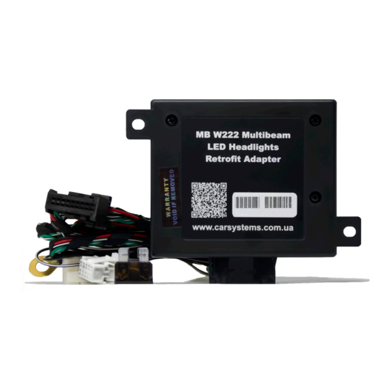
Introduction Preface This document guides you through the installation of the W222 Multibeam LED Headlights Retrofit Adapter – the device designed to match Multibeam LED Headlights with Mercedes Benz S-class cars 2013–2016 model years. Audience This document is intended for CarSystems customers, partners, and employees to get familiar with the W222 Multibeam LED Headlights Retrofit Adapter. -
Page 6: Preparation For Installation
Preparation for Installation Headlights QR-codes Take a high quality photo of two QR codes (watch Fig. 1) on the top of the Left headlight and Right headlight. These codes will be used in the coding process, send them to our technician. Don’t mount bumper until coding is finished. Fig. -
Page 7: Headlights Control Units
Fig. 4 PXL Headlight Control Unit. Fig. 4 Unmount Headlight Control Units appearance. Fig. 5 Location of HW and SW part numbers. Part numbers suitable with W222 Headlights HLI Headlight Control Unit: A 222 900 30 13 A 222 900 05 15... -
Page 8: Tail Lights Market Specification
Preparation for Installation Tail Lights Market Specification Different coding used for different car and tail lights market specification. There are two types of Tail Lights: ECE market specification and US market specification. ECE market specification Tail Lights have a white connector and the US market have a blue one. -
Page 9: Location
Preparation for Installation Location Recommended location for adapter installation is under the carpet of front passenger footwell zone. All necessary connection points are located there: Periphery CAN Potential Distributor x30/27 (hereinafter referred to as CAN Distributor), A-pillar fuse box (hereinafter referred to as Fuse Box), ground point. Fig. -
Page 10: Installation
Installation Adapter Installation As soon as CAN Distributor, fuse box and ground point identified, you can start the installation. Fig. 11 Adapter’s connectivity 10/16 Revision–4. 19 March 2021 CARSYSTEMS.COM.UA... - Page 11 Installation VERY IMPORTANT! MAKE SURE YOU DISCONECT ANY CHARGING EQUIPMENT BEFORE INSTALATION: car battery charger, notebook charger, etc. Use Fig. 11 as a guide to take the following steps: 1) Connect the black Negative Power Supply wire (A) from the adapter to the ground point.
-
Page 12: Tail Lights Connection
Installation Tail Lights Connection Following procedures and tail lights coding needed only in case of facelift tail lights installation. Route (E) Control wire (watch Fig. 11) to the trunk and connect to pin 9 of Left Tail Light and Right Tail Light 10 pin connector (watch Fig. 13), two white connectors are supplied with the adapter. -
Page 13: Coding
Coding Preparation for Coding The initial coding always done by our technician. The coding time must be reserved in advance. Make sure you have done the installation correctly and make sure you have everything required: mini USB data cable; laptop with a good internet connection and working USB port;... - Page 14 Coding Table 2 Troubleshooting Coding result Cause Solution Left headlight Right headlight module module module module ERROR ERROR One of the Turn ignition on and remove one by one 2 PIN CAN bus connectors headlight’s 2 PIN from the CAN Distributor, when the headlight connector is CAN bus connectors disconnected from the CAN Distributor the corresponding (F) is not identified...
-
Page 15: Operability Check
Operability check Operability Check After coding completion disconnect all equipment, turn off the ignition, close the car, and let it sleep for 5 minutes. To start operability check, call up Vehicle settings, select Locator illumination and switch function ON. Then select Exterior lighting delayed shut-off, set delay for 15s. - Page 16 Thank you for your attention For more information contact us. Revision–4. 19 March 2021 16/16 CARSYSTEMS.COM.UA...