
Related Manuals for Circutor OPTIM FRS P&P Series


Summary of Contents for Circutor OPTIM FRS P&P Series
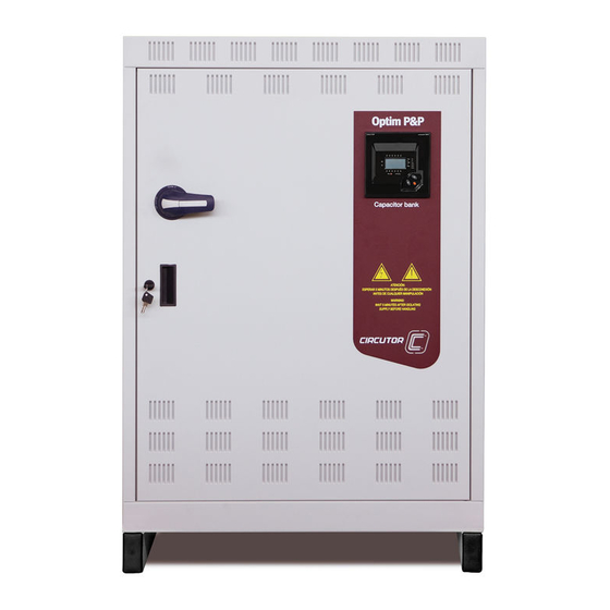
- Page 1 Low voltage capacitor banks with detuned filters, switched by contactors. OPTIM FRS/FR P&P series INSTRUCTION MANUAL (M090B01-03-19A)
- Page 2 OPTIM FRS/FR P&P series Instruction Manual...
-
Page 3: Safety Precautions
CIRCUTOR, SA reserves the right to modify features or the product manual without prior notifi cation. DISCLAIMER CIRCUTOR, SA reserves the right to make modifi cations to the device or the unit specifi ca- tions set out in this instruction manual without prior notice. -
Page 4: Table Of Contents
OPTIM FRS/FR P&P series CONTENTS SAFETY PRECAUTIONS ............................3 DISCLAIMER ................................3 CONTENTS ................................4 REVISION LOG ...............................5 1.- VERIFICATION UPON RECEPTION ......................... 6 1.1.- RECEPTION PROTOCOL ......................... 6 1.2.- TRANSPORT AND HANDLING ........................ 6 1.3.- STORAGE ..............................7 2.- PRODUCT DESCRIPTION ..........................8 3.- INSTALLATION ..............................8 3.1.- PRELIMINARY RECOMMENDATIONS .................... -
Page 5: Revision Log
OPTIM FRS/FR P&P series REVISION LOG Table 1: Revision log. Date Revision Description 10/15 M090B01-03-15A Initial Version Changes in the following sections: 03/16 M090B01-03-16A 3.9. Changes in the following sections: 04/16 M090B01-03-16B 3.9. Changes in the following sections: 11/19 M090B01-03-19A 3.2. -
Page 6: Verification Upon Reception
- The device manual - The installed regulator manual. If any problem is noticed upon reception, immediately contact the transport company and/or CIRCUTOR's after-sales service. 1.2.- TRANSPORT AND HANDLING The transport, loading and unloading and handling of the device must be car- ried out with proper precautions and using the proper manual and mechanical tools so as not to damage it. -
Page 7: Storage
OPTIM FRS/FR P&P series When unloading and moving the device, use a forklift with forks long enough to support the entire length of the base. Otherwise, the forks should be long enough to support at least ¾ of said depth. The forks must be flat and supported firmly by the base. Raise the cabinet by placing the forks underneath the profile that supports the device. -
Page 8: Product Description
OPTIM FRS/FR P&P series 2.- PRODUCT DESCRIPTION The purpose of this manual is to assist during the installation, start-up and maintenance of OPTIM FRS/FR P&P series low voltage (LV) capacitor banks with detuned filters, switched by contactors. Carefully read the manual to get the best performance from these devices. 3.- INSTALLATION 3.1.- PRELIMINARY RECOMMENDATIONS In order to use the device safely, it is critical that individuals who handle it follow... -
Page 9: Preparation
3.2.- PREPARATION The CIRCUTOR OPTIM FRS/FR P&P static capacitor banks come ready for easy installation and start-up. Remove the packaging of the device and verify that its electrical features are suitable for con- nection to the available mains. -
Page 10: Place Of Installation
OPTIM FRS/FR P&P series 3.3.- PLACE OF INSTALLATION It is important to maintain a minimum distance around the device to facilitate cooling. In self-supporting cabinets, the back and front sides of the cabinet must be kept at least 50 cm away from walls of other devices and structures to allow for ventilation. -
Page 11: Connection Of The Capacitor Bank To The Mains
OPTIM FRS/FR P&P series 3.4.-CONNECTION OF THE CAPACITOR BANK TO THE MAINS Check that the rated voltage of the capacitor bank matches the voltage between phases of the grid to which it is being connected. Also check the operating circuit voltage (contactors). (See “3.7.- AUXILIARY CON- TROL VOLTAGE”... -
Page 12: Power Circuit
OPTIM FRS/FR P&P series Figure 5: Cable entry points of the OPTIM FR P&P models. 3.5.-POWER CIRCUIT Connect input terminals L1, L2 and L3 (power circuit) to the mains using a cable with a suitable cross-section, in accordance with the LVR, ITC-BT-19. Generally, the phase cables are according to the following colour code: L1 (black), L2 (brown), L3 (grey). -
Page 13: Auxiliary Control Voltage
OPTIM FRS/FR P&P series 3.7.- AUXILIARY CONTROL VOLTAGE Control circuits are defined as those related with regulator output relays and the capacitor's operating contactors. These circuits are usually powered with a 230 V~ auxiliary voltage (most common). For all the standard models of the OPTIM FRS P&P and OPTIM FR P&P range, the auxiliary voltage is supplied from an internal AUTOTRANSFORMER: Does not require connection of the external neutral. - Page 14 OPTIM FRS/FR P&P series after the mains switch of the installation. To prevent excessive attenuation of the signal, it is recommended that the minimum cross-sec- tion of the secondary winding cable (terminals S1, S2) is at least 2.5 mm Figure 7: Current transformer (CT) connection terminals. Instruction Manual...
-
Page 15: Capacitor Bank Start-Up
OPTIM FRS/FR P&P series 4.- CAPACITOR BANK START-UP 4.1.- BEFORE START-UP The automatic capacitor banks include a power factor regulator. The operation of said regulator must be known prior to start-up; for this reason, all the capacitor banks include a specific manual for the regulator used. Ensure you have this manual available for the start-up process. -
Page 16: Checks Once The Capacitor Bank Has Been Connected And The Regulator Has Been Adjusted
OPTIM FRS/FR P&P series Figure 8: Plug&Play Computer Max Regulator. (Photo as an example, it may not coincide with the model used on your device). POWER 1 2 3 4 5 6 SUPPLY 400 V ac + C1 ... C6 Figure 9: Connection of a regulator with only one CT. - Page 17 OPTIM FRS/FR P&P series NOTE: For capacitor banks with filters, the capacitor's voltage exceeds the network voltage by a % that is approximately equal to the filter's overvoltage factor (p%). In fact, the capacitor's real overvoltage is: ∆ − 5.- To check the filter's correct tuning, make sure that the voltage on the terminals of each wind- ing of the reactor is: −...
-
Page 18: Maintenance
OPTIM FRS/FR P&P series 5.- MAINTENANCE 5.1.- SAFETY REGULATIONS Before operating the devices, follow the safety regulations indicated in section “ ” of this manual 3.1.- PRELIMINARY RECOMMENDATIONS The National Electric Code of the country where the capacitor bank is installed or operated should be strictly followed. -
Page 19: Key Points For Inspecting Contactors
OPTIM FRS/FR P&P series 5.2.2. KEY POINTS FOR INSPECTING CONTACTORS Check that the plastic parts are not blackened and do not show signs of burning or hardening. Check that the head is properly inserted. The terminals must be clean. If the capacitor bank includes RD discharge resistors, check that they are in good condition (they are not open and show no signs of burning). -
Page 20: Key Points For Inspecting The Regulator
OPTIM FRS/FR P&P series 5.2.4. KEY POINTS FOR INSPECTING THE REGULATOR Check that the regulator does not show signs of deterioration and the display is lit as normal. Inspect the cables and terminals. They should be clean and should not be hardened or over- heated. -
Page 21: Regulator Checks
OPTIM FRS/FR P&P series Table 3 (Cont.):Nominal consumption of the capacitor paths, by power and voltage In, Current Power 3 x 230 V ~ 3 x 400V~ 80 kvar 115 A Note: If consumption is ±25% less than that indicated in and the voltage is within the Table 3 tolerance limits, this is usually a sign of degradation of the capacitors. -
Page 22: Technical Features
OPTIM FRS/FR P&P series 6.- TECHNICAL FEATURES Electrical features Usage voltage and nominal frequency Un / fn, listed on the label Design voltage Un+ 10% (440 V for 400 V devices) Nominal power and distribution of steps Qn and composition, (see label) Total losses <... -
Page 23: Standard Electrical Diagrams
OPTIM FRS/FR P&P series Mechanical features Model OPTIM FRS P&P OPTIM FR4 P&P OPTIM FR6 P&P Dimensions (Width x Height x Depth) 800 x 1200 x 500 mm 900 x 1900 x 650 mm 1200 x 1900 x 650 mm Weight 128 Kg 460 Kg... - Page 24 OPTIM FRS/FR P&P series Figure 11: Standard electrical diagram of automatic capacitor banks in the OPTIM FRS P&P model. Instruction Manual...
- Page 25 OPTIM FRS/FR P&P series Figure 12: Standard electrical diagram of automatic capacitor banks in the OPTIM FR4 P&P model. Instruction Manual...
- Page 26 OPTIM FRS/FR P&P series Figure 13: Standard electrical diagram of automatic capacitor banks in the OPTIM FR6 P&P model. Instruction Manual...
- Page 27 OPTIM FRS/FR P&P series Figure 14: Standard electrical diagram of automatic capacitor banks in the OPTIM FR8 P&P model. Instruction Manual...
-
Page 28: Maintenance And Technical Service
• CIRCUTOR accepts no liability due to the possible damage to the unit or other parts of the installation, nor will it cover any possible sanctions derived from a pos- sible failure, improper installation or “improper usage”... -
Page 29: Ce Certificate
OPTIM FRS/FR P&P series 10.- CE CERTIFICATE Instruction Manual... - Page 30 OPTIM FRS/FR P&P series Instruction Manual...
- Page 31 OPTIM FRS/FR P&P series Instruction Manual...
- Page 32 CIRCUTOR, SA Vial Sant Jordi, s/n 08232 -Viladecavalls (Barcelona) Tel.: (+34) 93 745 29 00 - Fax: (+34) 93 745 29 14 www.circutor.es central@circutor.es...
Need help?
Do you have a question about the OPTIM FRS P&P Series and is the answer not in the manual?
Questions and answers