Table of Contents
Advertisement
Quick Links
AUTOMATION SYSTEMS
ACTUATORS FOR SWING GATES
Assembly instructions for the installer
DTM System spółka z ograniczoną odpowiedzialnością spółka komandytowa
ul. Brzeska 7, 85-145 Bydgoszcz
tel./fax. (52) 340-15-83, 340-15-84
www.dtm.pl, dtm@dtm.pl
version 1.2
DESIGN AND PRODUCTION
O F E L E C T R O N I C D E V I C E S
Advertisement
Table of Contents

Summary of Contents for DTM System DTM-SWIFT 350
- Page 1 AUTOMATION SYSTEMS ACTUATORS FOR SWING GATES Assembly instructions for the installer version 1.2 DTM System spółka z ograniczoną odpowiedzialnością spółka komandytowa ul. Brzeska 7, 85-145 Bydgoszcz tel./fax. (52) 340-15-83, 340-15-84 DESIGN AND PRODUCTION www.dtm.pl, dtm@dtm.pl O F E L E C T R O N I C D E V I C E S...
- Page 3 AUTOMATION MUST BE IMPLEMENTED IN ACCORDANCE WITH EUROPEAN STANDARDS: EN 12100 (Safety of machinery. Electrical equipment of machines. General requirements) EN 12445 (Gates. Safety in use of power operated doors. Test methods) EN 12453 (Gates. Safety in use of power operated doors. Requirements) The installer should provide the device with a residual current circuit breaker ensuring that the devices are disconnected from the power supply (EN 60335-1).
-
Page 4: Warranty
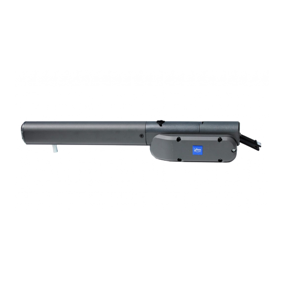
Please read these warnings carefully. The gate drive ensures correct and safe operation only if the installation and use comply with the following safety rules. DTM System is not responsible for accidents resulting from improper use or unprofessional installation of devices. - Page 5 1. Introduction 1.1. Basic information Electromechanical actuators are designed to control swing gates. The assembled and started system can be conveniently operated by radio transmitters. Make sure you have all the elements shown in Figure 1, and then read the entire manual. actuators two elements fixing the actuator's piston to the gate fitting two sets of elements fixing the actuator drive to the pillar fitting...
-
Page 6: Mechanical Assembly
DTM System remote gate controller external photocell Fig. 2. Illustrative view of the gate automation installation. CAUTION! The actuator must not work so that the piston extends or retracts to the end. A correctly set actuator makes a movement of up to 99% of stroke when the gate is closed and to 1% when the gate is open. - Page 7 CAUTION! The gate must operate smoothly and without impact, the movement must be smooth and unobstructed. Please note that the ground level may rise by several centimeters in winter. The gate should be stable and as far as possible free from play in order to prevent undesirable and swinging movements. Determine what materials are needed to install the kit and provide them before starting the installation.
- Page 8 2.4. Limiters swing gate requires a limiter in the OPEN and CLOSE directions. Stops protect the drive, gate and fittings against wear. Operating the gate without permanently fixed stops leads to its malfunction. It is often dangerous, this leads to premature wear and will invalidate the warranty! Fig 5.
- Page 9 DTM-SWIFT350 If it is not possible to achieve the dimensions given in the table, other dimensions can be (mm) (mm) (mm) (mm) (mm) determined - for the leaf opening 90 ° A = B (difference between A and B max. 4 cm) - to the 90°...
- Page 10 2.5. Pole fitting The correct position of the pillar fitting is decisive for the subsequent operation of the gate. The first step is to determine the distance between the motor pivot point and the gate pivot point (figure 7), and thus the opening angle (see point 2.3.).
- Page 11 2.6. Gate fitting The gate hardware must be mounted horizontally in relation to the pillar fitting (Fig. 9). The distance between the fittings is determined by the fixing dimension. When the gate is closed, the drive should perform a closing maneuver of 99%. When open, the drive should leave 1% stroke. Using the full travel of the actuator during operation may damage the actuator and void the warranty! The attachment dimensions must be complied with in all circumstances! (dimensions A and B).
-
Page 12: Electrical Installation
2.9. Maintenance The drive mechanics are maintenance-free. However, it is recommended that at regular intervals (monthly) check that the gate hardware and the drive are securely fastened. Loosen the drive and check that the gate is functioning properly. Remember that the drive cannot eliminate problems caused by a malfunctioning gate. -
Page 13: Acceptance Tests
230V Fig. 13. Location and description of connectors supplying the drive motor. 4. Acceptance tests ATTENTION! After installing the controller and all associated devices, especially safety devices, final tests should be made to check the entire automation. These tests should be performed by competent personnel who are aware of the risks involved! Final tests are the most important phase in the implementation of automation. - Page 14 DTM System hereby declares that the drive complies with the EU directives. The full text of the EU declaration of conformity is available at the internet address: www.dtm.pl CAUTION! The presented symbol informs that a given electric or electronic device, after its end of use, must not be disposed of with household waste.
- Page 16 D E S I G N A N D P R O D U C T I O N O F E L E C T R O N I C D E V I C E S DTM System spółka z ograniczoną odpowiedzialnością spółka komandytowa Ul. Brzeska 7, 85-145 Bydgoszcz, Polska http://www.dtm.pl...


Need help?
Do you have a question about the DTM-SWIFT 350 and is the answer not in the manual?
Questions and answers