
Related Manuals for Baltimore Aircoil Company ICE CHILLER TSU-M


Summary of Contents for Baltimore Aircoil Company ICE CHILLER TSU-M
- Page 1 MTSU-Mv06EN TSU-M ICE CHILLER® Thermal Storage Unit for internal melt OPERATING AND MAINTENANCE INSTRUCTIONS...
- Page 2 Recommended maintenance and monitoring programme ® Baltimore Aircoil Company's Ice Chiller Thermal Storage Units and Thermal Storage Coils have been developed for long, trouble-free service when installed, operated and maintained properly. To ensure optimal performance and ® maximum equipment life for your Ice Chiller Thermal Storage Unit, it is important that a regular inspection/maintenance program be developed and implemented.
-
Page 3: Table Of Contents
Table of contents OPERATING AND MAINTENANCE INSTRUCTIONS Construction details Ice Chiller® General information Operating conditions Connecting pipework Safety precautions Disposal requirements Non-walking surfaces Modifications by others Warranty Operating instructions General Information Start-up and commissioning procedures Daily Operating Guidelines Seasonal Shutdown Ice LogicTM Ice Quantity Controller Water Care About water care... -
Page 4: Construction Details
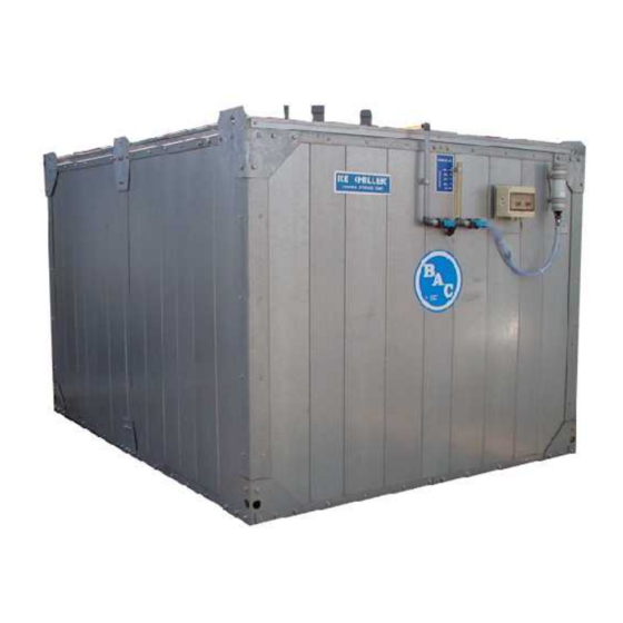
TSU-M CONSTRUCTION DETAILS Ice Chiller® INTERNAL MELT APPLICATION 1. Wall panel 2. Coil support beams 3. Glycol connections 4. Galvanised steel coil 5. Watertight covers 6. Primary liner 7. Extruded polystyrene insulation 8. Secondary liner/Vapor barrier 9. Sight tube Not shown: Ice Inventory Sensor - Ice Logic™ Ice Quantity Controller – Air pump 1 Construction details 1 Construction details W W W . -
Page 5: General Information
TSU-M GENERAL INFORMATION Operating conditions BAC cooling equipment is designed for the operating conditions specified below, which must not be exceeded during operation. • Wind Load: For safe operation of unshielded equipment exposed to wind speeds above 120 km/h installed at a height above 30 m from the ground, contact your local BAC-Balticare representative. -
Page 6: Safety Precautions
Safety precautions All electrical, mechanical and rotating machinery constitutes a potential hazard, particularly for those not familiar with its design, construction and operation. Accordingly, adequate safeguards (including use of protective enclosures where necessary) should be taken with this equipment both to safeguard the public (including minors) from injury and to prevent damage to the equipment, its associated system and the premises. -
Page 7: Non-Walking Surfaces
National and regional legislation for material disposal and protection of workers should be taken into account with regard to: • Appropriate handling of construction and maintenance materials when dismantling the unit. In particular when dealing with materials that contain harmful substances, such as asbestos or carcinogenic substances. •... -
Page 8: Operating Instructions
TSU-M OPERATING INSTRUCTIONS General Information To ensure dependable, trouble-free, efficient operation of the thermal storage units, each system is provided with factory installed, operating control assemblies. During normal operation a solid layer of ice at the top of the tank will not form. - Page 9 Ice Logic with radar sensor CAUTION Do not overfill! Overflowing the tank may damage the insulation and/or cause the operating controls to malfunction. 3. Continue to fill the tank slowly with a minimum of water turbulence until the water level in the sight tube corresponds with the zero water level indicated on the label.
-
Page 10: Daily Operating Guidelines
On multiple unit installations, once the initial ice build cycle has been completed, check all the sight tubes to verify the water levels in each tank are equal. If the inventories are significantly out of balance, the flow rates of the glycol solution to each of the thermal storage units should be checked and balanced. - Page 11 When properly set, the control box will provide a passive 4-20 mA output signal where 0 mA stands for 0% ice and 20mA corresponds with 100% ice (full ice build). 3 Operating instructions 3 Operating instructions W W W . B A L T I M O R E A I R C O I L . E U...
- Page 12 WIRING SPECIFICATION Terminal Fuse Description L-N220VAC / max 10VA supply Max. cable section is 2.5 mm2 1, 2, 3, 4 Sensor terminals (Wiring done by BAC). Wiring details see wiring diagram. 9, 10 4-20mA passive current loop output. External voltage: max. 24VDC / %o, 12VDC Max.
- Page 13 CAUTION Never operate the black control knob whenever the protective cover above the supply terminals is not properly installed. At initial start up the following screen is shown: In the terminal box of the controller, you can find a black knob. Pressing this knob or button results in activating a menu, a selected line or confirming your choice. Rotating the button allow to change values (dial) or navigate through the menu. The active line has a ">"...
- Page 14 Rotate the black button to dial 7 and press to confirm. The display indicates 'Range successfully changed'. In case the button is pressed without dialing 7 you return to the previous menu and values are not stored. After the range is entered, the following screen appears for a few seconds, followed by the next screen: Now follow the procedure to set the zero level.
- Page 15 The sample counter moves from 1 to 16 and then the next screen is shown: Rotate the black know to dial 7 and press to confirm the zero setting. The display shows 'Zero Level successfully changed' to confirm the setting. If the black button is pressed without dialing 7, the zero level is not stored. In case the sensor is not in the correct position (sensor too high or too low) to allow a correct full range measurement, the display will indicate an error first and the position of the sensor must be modified after which the procedure must be repeated.
- Page 16 START SCREEN / SCREEN AT NORMAL OPERATION The display shows the measured water level in mm and the percentage versus the range that was set to correspond with 100% ice. On line 2 and 3 the status of the low and high level alarm is shown. 'OK' means there is no alarm. If the water level is below the minimum level, the Low Level Alarm is activated and 'Alarm' is displayed on the screen. The output contact for low alarm (13/14/15) is also activated and the red LED for low alarm lights up.
- Page 17 By scrolling down you can see following additional lines: The '->' sign in front of the lines indicates which line is selected. The arrow up or down at the right of the screen indicates that more lines are available in the upper or lower area of the screen. To select or activate a line, press the black button.
- Page 18 Set Zero Level Activate to set the zero ice level value. Make sure you only do this when no ice is present in the ice tank and when the water level is at zero level of the sight glass. (For concrete tank applications make sure the water level is just above the coil header.) Rotate the black knob to change 'No' to 'Yes' and press to confirm your choice.
- Page 19 Show Range This allows you to see the range which corresponds to 100% ice level rise. For TSU-M models the range is typically 117 mm, for TSU-ML models this is typically 92 mm. This menu is only to view the range. Setting the range is another menu (Set Range).
- Page 20 Service Menu This menu allows to do additional factory settings which are not accessible by the standard user. If you enter the menu you get the following screen. Keep pressing the black button to exit. You can only enter with the correct code.
-
Page 21: Water Care
TSU-M WATER CARE About water care ® In the near freezing temperatures of the Ice Chiller Thermal Storage Unit, scale and corrosion are naturally minimized. Therefore, for the tank water side of the units, a water treatment program to prevent scale or corrosion is not normally needed, unless the water is corrosive in nature. -
Page 22: Special Water Treatment Considerations
To ensure that galvanized steel surfaces are passivated, for the first 6-8 weeks of operation, the pH of the tank water should be maintained between 7.0 and 8.2 and calcium hardness maintained between 100 and 300 mg/l (as CaCO ). The passivation is complete and effective when the new zinc surfaces turn dull grey in colour. If white deposits form on galvanized steel surfaces after the pH is returned to normal, this is a sign of white rust, and therefore, the passivation process should be repeated to insure proper passivation and maximum corrosion resistance. -
Page 23: Cold Weather Operations
TSU-M COLD WEATHER OPERATIONS About cold weather operation BAC equipment can be operated in subfreezing ambient conditions provided the proper measures are taken: 1. Insulation of piping. 2. Protection against coil freezing. 3. Elimination of ice due to sub-freezing ambient. Listed below are general guidelines which should be followed to minimize the possibility of freeze-up. -
Page 24: Ice Due To Subfreezing Ambients
% Ethylene Freeze protection -10°C -16°C -25°C -39°C Freeze protection of ethylene glycol solutions Glycol systems require specific inhibitors compatible with the materials of construction they come into contact with. These inhibitors generally come pre-mixed with the glycol additive for the cooling circuit. Ice due to subfreezing ambients ®... -
Page 25: Maintenance Procedure
TSU-M MAINTENANCE PROCEDURE General A program of regular inspection and maintenance is essential for optimum performance and maximum service life. The following information is provided as a guide to establishing such a maintenance program. If you have any specific questions, please contact your local BAC-Balticare service provider or representative whose name, e-mail and phone number can be found on the website www.BACservice.eu. - Page 26 Using good quality water (see section "About water care" on page 21),fill the tank following the steps outlined below. For proper, long-term operation of the thermal storage unit, the tank must be filled exactly to the prescribed level. 1. Remove the access cover on the top of the unit. Use a fill hose to fill the tank. See following table “Fluid volumes”...
-
Page 27: Inspections And Corrective Actions
Water level in sight tube 1. Fill initially to this level "0” 2. Percent ice build 3. Overflow 3. When the tank is filled, remove the fill hose, then replace and tightly secure the access cover. CAUTION Do not overfill! Overflowing the tank may damage the insulation and/or cause the operating controls furnished with the unit to malfunction. - Page 28 ICE CHILLER® TANK ® All Ice Chiller Thermal Storage Units are provided with sectional insulated tank covers, which, when kept in place, will minimize the accumulation of trash or debris in the tank. Quarterly, remove the access cover and inspect the interior of the unit for signs of scale formation, corrosion, or biological growth on the tube bundle.
- Page 29 Annually, have your glycol supplier check samples of the glycol solution for the proper level of inhibitors and adjust if necessary. 6 Maintenance Procedure 6 Maintenance Procedure W W W . B A L T I M O R E A I R C O I L . E U...
-
Page 30: Comprehensive Maintenance
TSU-M COMPREHENSIVE MAINTENANCE About comprehensive maintenance In order to ensure maximum efficiency and minimum downtime of your evaporative cooling system, it is recommended to establish and execute a programme of preventive maintenance. Your local BAC Balticare representative will assist you in establishing and implementing such programme. The preventive maintenance programme must not only avoid that excessive downtime occurs under unforeseen and unwanted conditions, it also ensures that factory authorized replacement parts are used, which are designed to fit and for their purpose carry the full factory warranty. -
Page 31: Further Assistance & Information
TSU-M FURTHER ASSISTANCE & INFORMATION Assistance BAC has established a specialized total care company called Balticare. The BAC Balticare offering involves all elements required to ensure a safe and efficient operation of your evaporative cooling products. For more details, contact your local BAC representative for further information and specific assistance at www.BaltimoreAircoil.eu More information REFERENCE LITERATURE... - Page 32 W W W . B A L T I M O R E A I R C O I L . E U...
- Page 33 W W W . B A L T I M O R E A I R C O I L . E U...
- Page 34 W W W . B A L T I M O R E A I R C O I L . E U...
- Page 35 W W W . B A L T I M O R E A I R C O I L . E U...
- Page 36 W W W . B A L T I M O R E A I R C O I L . E U...
- Page 37 W W W . B A L T I M O R E A I R C O I L . E U...
- Page 38 COOLING TOWERS CLOSED CIRCUIT COOLING TOWERS ICE THERMAL STORAGE EVAPORATIVE CONDENSERS HYBRID PRODUCTS PARTS, EQUIPMENTS & SERVICES www.BaltimoreAircoil.eu info@BaltimoreAircoil.eu Please refer to our website for local contact details. Industriepark - Zone A, B-2220 Heist-op-den-Berg, Belgium © Baltimore Aircoil International nv...
Need help?
Do you have a question about the ICE CHILLER TSU-M and is the answer not in the manual?
Questions and answers