Advertisement
Quick Links
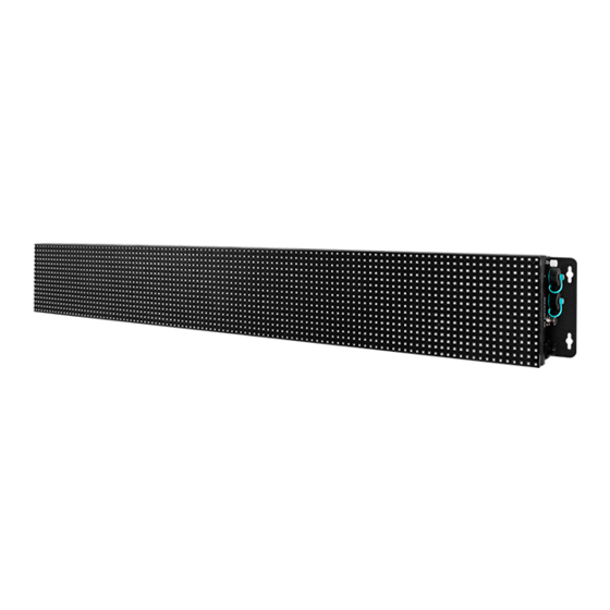
iKAN-116(A)-IP65/iKAN-124(A)-IP65 Quick Start
Packing List
In addition to this guide, the package includes the following items:
iKAN-116(A)-IP65/iKAN-124(A)-IP65
RJ-45 Connector x 2
Waterproof Assembly
Technical Support
service@icpdas.com
www.icpdas.com
Installation Guide
For Desktop Web
LED Display
Power Connector
Model Name
Wall Mounting
Resour ces
How to search for drivers, manuals and
spec information on ICP DAS website.
For Mobile Web
Model Name
v1.0, August 2020
Kit x 2
I/O Cable
Screw
Driver
M4x6L
Screw x 8
P1
Advertisement

Related Manuals for ICP DAS USA iKAN-116-IP65


Summary of Contents for ICP DAS USA iKAN-116-IP65
- Page 1 iKAN-116(A)-IP65/iKAN-124(A)-IP65 Quick Start v1.0, August 2020 Packing List In addition to this guide, the package includes the following items: iKAN-116(A)-IP65/iKAN-124(A)-IP65 Wall Mounting Screw LED Display Kit x 2 Driver RJ-45 Connector x 2 Power Connector M4x6L Waterproof Assembly I/O Cable Screw x 8 Resour ces Technical Support...
- Page 2 I/O Connector Power Connector Installing and Connecting the RJ-45 Connector The IKAN-116-IP65/iKAN-124-IP65 is equipped with an RJ-45 waterproof connector that is optional for use with E1 and E2 port. It can effectively protect the connection points from weather and climate.
- Page 3 3. Wrap the Gasket around the Clamping Ring 4. Wrap the Screw Nut around the Clamping Ring 5. Insert the Seal into the Clamping Ring...
- Page 4 6. Push the Sealing Nut forward and Hand-tighten it to seal the assembly 7. Insert the RJ-45 cable into the RJ-45 connector 8. Insert the Ethernet cable and screw the RJ-45 waterproof into the receptacle Hub/Switch Ethernet Port...
- Page 5 Installing, Wiring and Connecting the I/O Connector The IKAN-116-IP65/iKAN-124-IP65 is equipped with an I/O cable that provides access to RS-232, RS-485 and digital I/O signals. Wiring and Insert the I/O cable into the receptacle RS-232 x 1 RS-485 x2 I/O Connector...
- Page 6 2. Insert two conductors into the holes on the Cord Connector. See the table below for the correct pin-out connections. No. Pin-out Cord Connector 3. Wrap the Lock Nut around the Cord Connector 4. Insert the Gasket into the Clamping Ring...
- Page 7 5. Wrap the Clamp Ring around the Cord Connector 6. Insert the Seal into the Clamp Ring 7. Push the Sealing Nut forward and Hand-tighten it to seal the assembly...
- Page 8 8. Wrap the O-Ring around the Cord Connector O-Ring 9. Insert the power cable and screw the power waterproof into the receptacle Power Connector Power Supply (100 ~240 V...