RADAC WaveGuide 5 User Manual
Onboard explosion proof
Hide thumbs
Also See for WaveGuide 5:
- User manual (48 pages) ,
- User manual (35 pages) ,
- User manual (45 pages)
Table of Contents
Advertisement
Quick Links
Advertisement
Table of Contents

Related Manuals for RADAC WaveGuide 5


Summary of Contents for RADAC WaveGuide 5
- Page 1 WaveGuide Onboard Explosion Proof User Manual...
- Page 3 WaveGuide Onboard Explosion Proof User Manual Applicable for product number: WG5-OB-EX Related to software versions: wob 5.1 Version 5.1-1 of Dec. 2018 Radac B.V. Elektronicaweg 16b 2628 XG Delft The Netherlands tel: +31(0)15 890 3203 e-mail: info@radac.nl website: www.radac.nl...
- Page 5 Preface This user manual and technical documentation is intended for engineers and technicians involved in the software and hardware setup of the WaveGuide 5 Onboard system, Explosion Proof version (WG5-OB-EX). Note All connections to the instrument must be made using shielded cables. The shielding must be grounded at both ends of the cable.
-
Page 7: Table Of Contents
Contents Preface Introduction 1 Safety and Security 1.1 General ........1.2 Safety Conventions . - Page 8 Step 3. Configuration ....... . . Step 3.1: Set system date and time ......Step 3.2: Adjust network settings .
-
Page 10: Introduction
UDP messages. This manual describes the Explosion proof version of the WaveGuide Onboard system. Please refer to the Radac website for all other manual versions. Warning Do not use the instrument for anything else than its intended purpose. -
Page 12: Safety And Security
Chapter 1 Safety and Security General For the correct and safe installing of this product, it is essential that all personnel follow generally accepted safety procedures in addition to the safety precautions specified in this document. Safety Conventions 1.2.1 Warnings The following warning box is used within this document to urge attention in order to prevent personal injuries or dangerous situations. -
Page 13: Ec Declaration Of Conformity (For Eu)
Additional Information If you require additional information, contact Radac or its representative. Liability The information in this installation guide is the copyright property of Radac, The Nether- lands. Radac disclaims any responsibility for personal injury or damage to equipment caused by: •... -
Page 14: Labels
The contents, descriptions and specifications in this user manual are subject to change without notice. Radac accepts no responsibility for any errors that may appear in this Installation Guide. Caution Modification to the instrument may only be carried out by trained personnel that are authorized by Radac BV. -
Page 15: Personal Safety
Personal Safety Warning In hazardous areas it is compulsory to: • use personal protection and safety gear such as a hard hat, a fire-resistive overall, safety shoes, safety glasses and working gloves. • Avoid possible generation of static electricity. • Use non-sparking tools and explosion-proof testers. •... -
Page 16: Working Environment
1.7.3 Working Environment Hazardous Zone Warning POTENTIAL ELECTROSTATIC CHARGING HAZARD Avoid the generation of static electricity. Electrostatic charge/discharge of the device from/to a person or a tool could ignite a surrounding hazardous atmosphere. Safe Zone Warning Make sure that no explosive gas mixtures build up in the working area. 1.7.4 Required Skills Warning... -
Page 17: Grounding
• Cables and cable glands for at least 80 [C] (176 [F]) shall be used, unless ambient ◦ ◦ temperature is known to be always less than 50 [C] (122 [F]). ◦ ◦ 1.8.2 Grounding Warning Make sure the housing of the device is properly connected to the ground reference! Make sure the electrical resistance of the ground connection is below the maximum prescribed by local requirements! Accordance with Regulations... -
Page 18: Radar Positioning And Installation
Chapter 2 Radar positioning and installation Positioning For obtaining the best results from a WaveGuide Onboard the following radar positioning criteria must be taken into account: • It is advised to choose a mounting position such that the WaveGuide radar beam is free of large reflecting obstacles (the beam of the F08 antenna has a 5 [deg] half top angle ◦... -
Page 19: Installation
While the other end is a pin wrench that can be used for tightening the radar housing to the antenna. Upon request, Radac can supply an optional frame (Part no. WG-MH-EX) that allows for mounting the WaveGuide radar and mounting plate at angles 0, 5, 10, 15 and 20 [deg] away from vertical (see Fig.2.6). -
Page 20: Cable
• The cable must be shielded and can have a maximum length of 80 [m]. Figure 2.7: Block diagram of the Upon request, Radac can supply an optional cable that com- Waveguide Onboard system. plies with the WaveGuide system requirements for power and data transmission. -
Page 21: Housing
Housing To access the WaveGuide radar case: • Open cover A as shown in Fig.2.8. • Open and remove cover B as shown in Fig.2.9. • Use an 8 [mm] Allen key to loosen the 16 bolts of the housing. Make sure the 4 bolts on the side of the hinge are entirely screwed into the cover and do not protrude Figure 2.8: Cover A. -
Page 22: Closing Housing
The poles numbered 06 and 07 labeled RFL:LED+ and RFL:LED- are pre-connected to a status indicating LED. Upon powering the system the status LED will turn on and continue to shine while the system is starting up. When the startup process is completed and the system is running in normal mode the LED will blink every 4 [sec] ( 2 seconds on and 2 seconds off). -
Page 23: Waveguide System Commissioning
Chapter 3 WaveGuide system commissioning With all the wiring in place as described in the previous chapter, the system can be con- figured using the following steps (explained in the current chapter): 1. Connect the WaveGuide system to a computer. 2. -
Page 24: Step 1. Connect The Waveguide System To A Computer
Step 1. Connect the WaveGuide system to a computer Once the WaveGuide system is connected to a Local-Area-Network, communication can be done via the available web interface (Fig. 3.1). For this purpose any web browser with JavaScript enabled can be used. Figure 3.1: The web interface of the WaveGuide system. -
Page 25: Step 2. Become An Authorized User
In that case, the authorization data will be submitted automatically by the browser without a pop-up dialog. The default login password is “radac”. After successful authorization, the user can view and change settings. After submitting any new settings a reboot dialog will appear. -
Page 26: Step 3.1: Set System Date And Time
If the WaveGuide is not connected to the Internet but instead connected to a local network that includes a time server, then the WaveGuide system can be adjusted to synchronize time and date with the local time server. For more information regarding such an adjustment please contact Radac. -
Page 27: Step 3.2: Adjust Network Settings
Step 3.2: Adjust network settings Figure 3.3: Adjusting the network settings. The default IP address can be modified via the web interface (Fig. 3.3). It is advised to use the default settings, to automatically obtain the network settings from a DHCP server, and to ensure that the system will receive the same IP address from the DHCP server at all times. -
Page 28: Step 3.3: Sensor Configuration
Step 3.3: Sensor configuration The WaveGuide Onboard is designed with a high level of flexibility in mind, to apply to every possible mounting situation. The sensor menu as shown in Fig. 3.4, allows the configuration of the parameters that are specific to the sensor mounting position. Figure 3.4: Setting sensor parameters (changes only take effect after the system is rebooted). - Page 29 Min. range The range minimum is the minimum distance at which the sensor will detect the water level. This parameter is used to avoid spurious measurements and should be set depending on the installation location. If there are any nearby surfaces that can reflect the radar signal the range minimum should be set to a value higher than the distance to those reflecting surfaces.
-
Page 30: Step 4: Perform System Check
Step 4. Perform system check This section explains how to inspect the quality of measurements after configuring and rebooting the WaveGuide system (the start-up process can take up to 5 minutes). Step 4.1: Check system information The system information table can be reached through the status menu item on the top-right of the web interface. -
Page 31: Step 4.2: Check Reflection Diagrams
Step 4.2: Check reflection diagrams The reflection diagram of the radar can be accessed via the sensor configuration page by clicking on the corresponding "reflection" button (Fig. 3.7). A reflection diagram is a graphic representation of a single measurement, where the signal strength [dB] is plotted against the measurement distance [m]. -
Page 32: Step 4.3: Check Measurements
Step 4.3: Check measurements The ’Dashboard’ page, gives the possibility to view plots of different measured and calcu- lated parameters. Please note that, as a result of calculations preformed some parameters are shown with a constant delay such as heaveIMU and heaveWOB (100 and 120 [sec] of delay). -
Page 33: Step 5: Configure Distribution Of Data
Default message format The Default format starts a new line for each parameter in the subscription. The time used in the Radac format is Unix Epoch time in milliseconds (UTC time in milliseconds since 00:00:00 on the 1 of January 1970). Each line in the Default format ends with a Line-Feed character (char10). - Page 34 Format01 message format The Format01 message, formerly called the SESAM format, used by the Dutch Ministry of Infrastructure and the Environment (Rijkswaterstaat), is only defined for the heave and the 10 second mean (H parameter). It consists of 8 character lines (Line-Feed character + status character + sign character + 4 character value in cm + Carriage-Return character).
-
Page 35: Step 6: Technical Assistance
Please note that it can take up to 3 minutes to generate and download the diagnostics file and that it can contain up to 100 [kB] of data. It is recommended to share the diagnostics file with Radac B.V. because it can help with providing future technical support. -
Page 36: Using The System
Dutch government for wave height analysis. It also meets the standards set by The International Association of Oil & Gas Producers (OGP). A detailed description of the SWAP package is available on the Radac website (http://www.radac.nl). - Page 37 IP address". The Login name and password for FTP access are the same as the user-name and password for modifying settings (by default both user-name and password are ’radac’) Figure 4.1: Data logger page. The folder structure used for data logging is one directory per sub-system. In this directory, sub-directories are created that contain the raw data and parameter files (one file per day...
-
Page 38: Appendix 1: System Parameters
Appendix 1: System parameters Available parameters Tables 1 to 6, describe all the parameters that are measured and calculated by the Wave- Guide Onboard system. Name Description Unit heaveRadar Instantaneous uncompensated water level heaveIMU Instantaneous radar position along vertical line heaveWOB Instantaneous ship motion compensated water level Table 1: Raw data, heaveRadar, heaveWOB and heaveIMU at 10Hz Name Description... - Page 39 Name Description Unit H1/3 Average height of the highest 1/3 of the waves TH1/3 Average period of the highest 1/3 of the waves H1/10 Average height of the highest 1/10 of the waves H1/50 Average height of the highest 1/50 of the waves T1/3 Average period of the longest 1/3 of the periods Average height of all waves...
-
Page 40: Appendix 2: System Specifications
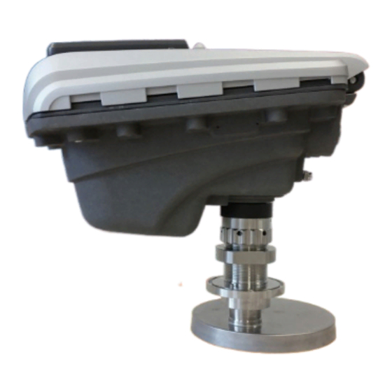
Appendix 2: System specifications Mechanical Weight 18.5 [kg] (incl. antenna 2.8 [kg]) Casing material Chromatized aluminium Electrical Radar frequency 9.319 – 9.831 [GHz] Modulation Triangular FMCW Emission The emitted microwave energy is far below acceptable limits for exposure of the human body. Depending on the type of antenna, a maximum radiation of 0.1 [mW] is generated. - Page 41 Figure 2: WaveGuide Explosion Proof dimentions.
Need help?
Do you have a question about the WaveGuide 5 and is the answer not in the manual?
Questions and answers