
Subscribe to Our Youtube Channel
Related Manuals for technetix AIMA3000-FT5E


Summary of Contents for technetix AIMA3000-FT5E
- Page 1 AIMA3000-FT5E 1550 NM FORWARD TRANSMITTER ENHANCED Product User Manual Online Email: customer.service.vdl@technetix.com Website: technetix.com Technetix Group Limited Oct/2017 - V1...
-
Page 2: Table Of Contents
5.4 Module Upgrades ......................................21 CAUTION ....................................22 5.5 Module Operating Range ..................................22 5.5.1 94CH QAM (including OFDM) Environment ..........................22 6 Troubleshooting ................................23 8 Declaration of Conformity ............................24 Appendix A: Description of LED Indicator Lights .......................25 Oct/2017 - V1 Technetix Group Limited... -
Page 3: Manual Guide
Outage or overload requiring service and repairs: Unplug the unit and refer only to Technetix's qualified service personnel. Servicing and repairs: DO NOT attempt to service this unit yourself. Refer all servicing needs to Technetix's qualified service personnel only. WARNING! Exposure to class 3A laser radiation is possible. -
Page 4: Related Documentation
- Technetix.NMS3-EPSM - Basic Alarm Management - Technetix.NMS3-EPSM - Basic System Management - Technetix.NMS3-EPSM - Basic Template Management 1.3 Technical Support If you need help in the process of setting up and maintaining an FT5E, please contact Technetix’s technical support staff: Europe: Technetix BV... -
Page 5: Introduction
2 Introduction 2.1 Overview The 1550 nm Forward Transmitter – Enhanced (FT5E) is designed to plug into the Technetix latest Advanced Intelligent Multi-services Access platform – the AIMA3000. The FT5E supports DOCSIS 3.1 technical standards. It allows for broadcast and narrowcast dual RF inputs, providing individual amplifying and transmission gain configuration for each circuit. -
Page 6: Specifications
3. Two ports for NC inputsand two for laser RF level. 4. CNR/CSO/CTB are tested with 77 NTSC CW channels (55.25MHz-547.25MHz). MER and BER are tested with 110 QAM256. All parameters are measured using a Technetix reference receiver, 10 km fibre, and 0 dBm input level. -
Page 7: Order Details
LC/APC FC/APC E2000/APC Bandwidth 45-1218 MHz 1. Default spacing is 200 GHz. For other wavelength configurations not listed, please contact Technetix. 2. Standard option. Contact a Technetix sales representative for availability of other options. Oct/2017 - V1 Technetix Group Limited... -
Page 8: Technical Description
Total OMI To back panel and comms Connection chassis back panel (module power supply and communication interface) Microprocessor Laser Laser Optical output 1 Optical output port 1 Optical output 2 Optical output port 2 Oct/2017 - V1 Technetix Group Limited... -
Page 9: Ft5E Module Structure
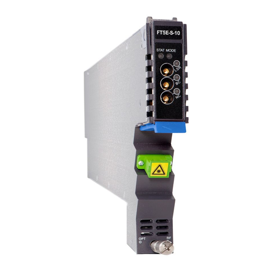
Product User Manual AIMA-FT5E 3.2 FT5E Module Structure 3.2.1 FT5E Module Appearance Figure 3-2 FT5E module 3.2.2 FT5E Module Front/Back Panel Layout Figure 3-3 FT5E front panel layout Figure 3-4 FT5E back panel layout Oct/2017 - V1 Technetix Group Limited... - Page 10 Broadcast input port 2 Air vent Multi-pin port Connection chassis back panel (module power) Alignment pin For easier positioning during module installation WARNING! When the FT5E is operating, the optical output port will produce non-visible laser radiation. Oct/2017 - V1 Technetix Group Limited...
-
Page 11: Installation
On receiving your new FT5E, carefully unpack and examine the contents for damage or loss that may have occurred during shipping. If any items are missing or damaged, refer to the product warranty terms and contact Technetix. The FT5E package should consist of the following:... -
Page 12: Ft5E Wiring
2. The FT5E module’s 'NC RF Total Input Power' alarm is set to 'off' by default. Before checking the RF indicator lights, log in to the AIMA3000 configuration system and turn on the main and secondary alarms (select HiHi/Hi/Lo/LoLo threshold values). 3. See AIMA3000 Manual for information about using the fibre guide and wiring fibre optic cables. Oct/2017 - V1 Technetix Group Limited... - Page 13 Always inspect the fibre-end interfaces using an appropriate scope to validate that the surfaces are adequately clean, free from damage, and dry from any solvents prior to connection. SC one click cleaning pen www.oneclickcleaner.com Oct/2017 - V1 Technetix Group Limited...
-
Page 14: Led Indicator Lights
1. The FT5E module’s 'NC RF Total Input Power' alarm is set to off by default. When the BC RF total input power is normal, the RF indicator light remains green. Before checking the RF indicator lights, log in to the AIMA3000 configuration system and turn on the main and secondary alarms (select HiHi/Hi/Lo/LoLo threshold values). Oct/2017 - V1 Technetix Group Limited... -
Page 15: Module Configuration And Alarms
AIMA-FT5E 5 Module Configuration and Alarms The FT5E module can be configured via the ASMM web interface or Technetix web-based NMSE system. This manual only provides instructions for configuration using the ASMM web interface. See the NMSE manual for configuration using Technetix web-based NMSE system. - Page 16 When the ' A pply' button is pressed, all FT5E settings are cleared and restored to default. After this process is 'Factory Defaults' completed, the module is automatically rebooted. 'Reboot' Reboots the module. This action requires approximately 20 seconds. Oct/2017 - V1 Technetix Group Limited...
-
Page 17: Ft5E Port Configuration Details
5.1.2 FT5E Port Configuration Details The port configuration interface is opened by selecting a port name under the FT5E module in the list on the left side, as shown in Figure 5-2. Figure 5-2 FT5E port configuration interface Oct/2017 - V1 Technetix Group Limited... - Page 18 'Prohibit Alarm'; when the 'Laser Output Control' is 'off', no alarm is triggered and the Parameter 3 'Laser Output' indicator light on the module’s alarm status interface is green. Default: 'Set as the Main Alarm'. Oct/2017 - V1 Technetix Group Limited...
-
Page 19: Automatically Uploading/Downloading Module Configuration
Automatic uploading of the FT5E’s current configuration files to the ASMM module’s database. Manual setting of all parameters in the module configuration interface and module port configuration interface 'Manual' (for details, see Chapters 5.1.1 and 5.1.2). Oct/2017 - V1 Technetix Group Limited... -
Page 20: Alarms
Press 'Refresh' to refresh information about the alarm status for each parameter of the FT5E module. See Table 5-3 for indicator lights corresponding to alarms of different levels. Table 5-3. Indicator lights for alarms of different levels Normal (No Alarm) Secondary Alarm Main Alarm Indicator light status Oct/2017 - V1 Technetix Group Limited... -
Page 21: Ft5E Port Alarms
AGC alarm status. See Table 5-3 for details about indicator light statuses for alarms of different levels. Press 'Refresh' to refresh information about alarm status for each parameter in the FT5E module. Oct/2017 - V1 Technetix Group Limited... -
Page 22: System Logs
If 'Delete All' is pressed, a prompt will appear asking ' A re you sure you want to delete all logs?' Select 'Confirm' to the delete all log records, or select 'Cancel' to cancel the operation. Oct/2017 - V1 Technetix Group Limited... -
Page 23: Module Upgrades
'Start Upgrade' to upgrade the firmware. Note: Before upgrading the module, download the latest module firmware from Technetix website. The module upgrade function in the web-interface does not support remote management. Use Technetix NMSE web-based software to automatically update, back-up, and restore FT5E configuration details. See the NMSE User Manual for more information. -
Page 24: Caution
Figure 5-8 MER and BC input changes 1. Optical input power to EDFA is 5dBm, optical input power to fibre is 16.4 dBm; fibre optic cable 12 km; optical input into the receiver -5 dBm. Oct/2017 - V1 Technetix Group Limited... -
Page 25: Troubleshooting
Adjust input signal power to achieve normal BC input signal. If the BC input power comparatively low or high is normal but the alarm is still on, contact technetix technical support. BC input power value is either too Adjust input signal power to achieve normal BC input signal. If the BC input power low or too high is normal but the alarm is still on, contact Technetix technical support. -
Page 26: Declaration Of Conformity
8 Declaration of Conformity According to ISO/IEC Guide 22 and EN45014 Manufacturer's Name: Technetix Manufacturer’s Address: Technetix Ltd, Innovation House, Technetix Business Park, Albourne, West Sussex, BN6 9EB Product Name: OPSW – Optical A/B Protection Switch Conforms to the following standards:... -
Page 27: Appendix A: Description Of Led Indicator Lights
Steady light Laser 1 main alarm (HiHi/LoLo) Steady light Steady light Laser 1 secondary alarm (Hi/Lo) Steady light Steady light Laser 2 main alarm (HiHi/LoLo) Steady light Laser 2 secondary alarm (Hi/Lo) Steady light Oct/2017 - V1 Technetix Group Limited...
Need help?
Do you have a question about the AIMA3000-FT5E and is the answer not in the manual?
Questions and answers