
Related Manuals for technetix AIMA3000.FT5S


Summary of Contents for technetix AIMA3000.FT5S
- Page 1 AIMA3000.FT5S 1510 nm Single Optical Forward Transmitter Module Product User Manual May/2016 - Version 1.0...
- Page 2 AIMA3000.FT5S Product User Manual AIMA3000.FT5S 1510 nm Single Optical Forward Transmitter Module Product User Manual Technetix Group Limited May/2016 - Version 1.0 sales@technetix.com • technetix.com...
-
Page 3: Table Of Contents
AIMA3000.FT5S Product User Manual Contents About This Manual ..............................5 Chapter Overview ....................................5 Related Documentation ..................................5 Document Conventions ..................................5 Technical Support ....................................6 Precautions .................................7 Overview ..................................8 Product Description ....................................8 3.2 Product Key Features ....................................8 3.3 Specifications ......................................9 3.4 Order Details ......................................12 Module Characteristics ............................14... - Page 4 AIMA3000.FT5S Product User Manual Module Configuration & Alarm setup ........................31 Port Configuration screen ..................................31 6.1.1 Determine RF power to RF input port .............................33 6.2 Applying RF settings to FT5S transmitter MGC mode ........................37 6.2.1 Sample RF load 80 channels analogue RF load .........................37 6.2.2 Sample RF load 42 channels analogue RF load ........................37...
-
Page 5: About This Manual
AIMA3000.FT5S Product User Manual 1 About This Manual 1.1 Chapter Overview About This Manual: Preface Precautions Overview: Application module overview, including the module features, technical specifications and ordering information. Module Characteristics: The appearance of the equipment, port and introduction of other components Installation: Installation procedure Module Configuration &... -
Page 6: Document Conventions
‘*’ Asterisk: Points marked with an asterisk means there is a corresponding note on the page 1.4 Technical Support If you need help in the process of setting up and maintaining an FT5S, please contact Technetix’s technical support staff: Europe:... -
Page 7: Precautions
Outage or overload requiring service and repairs Unplug the unit and refer the servicing to Technetix qualified service personnel only. Servicing and repairs DO NOT attempt to service this unit yourself. Refer all servicing needs to Technetix qualified service personnel only. WARNING! Exposure to class 3A laser radiation is possible. -
Page 8: Overview
3 Overview 3.1 Product Description The 1550 nm Forward Transmitter Module - Standard series (FT5S) is designed to plug into Technetix latest generation Advanced Intelligent Multi-services Access platform - the AIMA3000. Technetix AIMA3000 FT5S is available in single, dual, and quad laser configurations. It features advanced forward transmitters engineered for multi-service operators (MSOs) to increase network capacity to satisfy an ever-growing subscriber demand for more bandwidth. -
Page 9: Specifications
AIMA3000.FT5S Product User Manual 3.3 Specifications Optical Performance Optical wavelength 1510 nm ± 5 nm or ITU wavelength Optical outputs 1, 2 or 4 Output power 8 dBm, 9 dBm, or 10 dBm Optical connector SC/APC , LC/APC, FC/APC Laser RIN <... - Page 10 (5) CNR, CSO, CTB and MER are loaded with 30 NTSC+124 QAM256 or 30 PAL D/K+85 QAM256. BER is loaded with 30 NTSC+124 QAM256, 30 PAL D/ K+85 QAM256 or 153 QAM256. All are measured with Technetix referenced optical receiver with 5 km single-mode optical fibre 0 dBm.
- Page 11 AIMA3000.FT5S Product User Manual Figure 1 Block diagram FT5S Table 3-3 FT5S Block Diagram Glossary Parameters Glossary Narrowcast input ATTEN Attenuator -20 dB TP -20 dB test point Broadcast Input OMI ADJ TO BACK PLANE AND COMMS Data bus -20 dB OMI TP...
-
Page 12: Order Details
AIMA3000.FT5S Product User Manual 3.4 Order Details AIMA-FT5S-[V]-[W]-[X1X2]-[Y]-[Z] Forward transmitter 1510 nm module Options: Number of Optical Ports Single port Dual ports Quad ports Optical Output Power 8 dBm (6.3 mW) optical power 9 dBm (8 mW) optical power 10 dBm (10 mW) optical power... - Page 13 X2 used only in dual transmitter versions. Dual version, X1 is first channel and X2 is the second channel. Quad version, X1 is first channel and X2 is fourth channel (the second is 200 GHz higher than the first, the third channel is 200 GHz higher from the second).Contact Technetix Representatives for detailed optical information.
-
Page 14: Module Characteristics
AIMA3000.FT5S Product User Manual 4 Module Characteristics 4.1 Module Appearance and Port Layout 4.1.1 Overview Front Panel Rear Panel Figure 4-1 Module Appearance Technetix Group Limited May/2016 - Version 1.0 sales@technetix.com • technetix.com... -
Page 15: Front Panel Layout
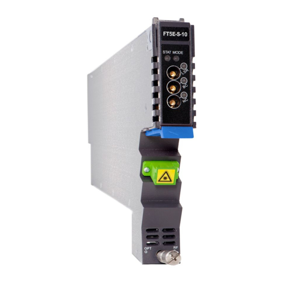
AIMA3000.FT5S Product User Manual 4.1.2 FT5S-S Front Panel Layout Figure 4-2 FT5S Front Panel Layout Technetix Group Limited May/2016 - Version 1.0 sales@technetix.com • technetix.com... - Page 16 AIMA3000.FT5S Product User Manual Table 4-1 FT5S-S Front Panel Functions Serial Number Item Description Module gain control mode indicator MODE LED MGC: Green Light Blinking AGC: Green Module alarm indicator Normal: Green STATUS LED Minor Alarm: Orange Major Alarm: Red...
-
Page 17: Rear Panel Layout
AIMA3000.FT5S Product User Manual 4.1.3 FT5S-S Rear Panel Layout 4.1.3 FT5S-S Rear Panel Layout Table 4-2 FT5S-S Rear Panel Functions Serial Number Item Description NC IN Narrowcast RF input BC IN Broadcast RF input Air vent Module air vent allowing air to flow out of the module... - Page 18 AIMA3000.FT5S Product User Manual 4.1.4 FT5S-D Front Panel Layout Figure 4-4 Front Panel Layout Technetix Group Limited May/2016 - Version 1.0 sales@technetix.com • technetix.com...
- Page 19 AIMA3000.FT5S Product User Manual Table 4-3 FT3S-D Front Panel Functions Serial Number Item Description Module gain control mode indicator MODE LED MGC: Green Light Blinking AGC: Green Module alarm indicator Normal: Green STATUS LED Minor Alarm: Orange Major Alarm: Red...
- Page 20 AIMA3000.FT5S Product User Manual 4.1.5 FT3S-D Rear Panel Layout Table 4-4 FT3S-D Rear Panel Functions Serial Number Item Description NC1 IN Narrowcast RF input BC1 IN Broadcast RF input NC2 IN Narrowcast RF input BC2 IN Broadcast RF input Air vent...
-
Page 21: Installation
Before installing this device, you must ensure that the unit is intact and ready for installation. Unpack and check the unit: Open the box to check for any damage that may have occurred during shipment. If damage is found, please contact a Technetix customer support representative. Necessary equipment and tools for installation:... -
Page 22: Module Installation
AIMA3000.FT5S Product User Manual 5.3 Module Installation Gently depress the orange retaining clip and release the hinged tab Hinged tab AIMA Module Orange retaining clip 2. Hold the AIMA module casing upright, align it with the AIMA3000 slide rails for the correct slot, and insert the module until it reaches the multi-pin connector. -
Page 23: Connecting Optical Cabling
AIMA3000.FT5S Product User Manual After the module is inserted, gently push the hinged tab until it snaps into the orange retaining clip. While ..pushing down on the hinged tab, the AIMA module will mate with the power bus and will lock in into the chassis. - Page 24 AIMA3000.FT5S Product User Manual Then, pull the panel forward. Then lift up the handle and slide the fibre guide out of the front of the chassis. Technetix Group Limited May/2016 - Version 1.0 sales@technetix.com • technetix.com...
-
Page 25: Using The Fibre Tray
AIMA3000.FT5S Product User Manual DO NOT remove the dust cap from the fibre connector until right before connecting it to the input port. Raise the clip, insert the fibre connector, and then lower the clip over the connector. When using the sliding guide, put the fibre connector in the clip and slide it in from the rear to the front, through the chassis. - Page 26 AIMA3000.FT5S Product User Manual Use the Fibre Guide Tool to organise the cables and wires in the fibre tray to prevent tangles and the ..blocking of the guide rails. Fibre Tray Area Cut-outs Technetix Group Limited May/2016 - Version 1.0 sales@technetix.com...
-
Page 27: Cleaning The Fibre Connector Ends And Front-Panel Optical Ports
AIMA3000.FT5S Product User Manual 5.4.3 Cleaning the Fibre Connector Ends and Front-panel Optical Ports To obtain a good quality optical input signal, optical fibre input ports and fibre connector ends must be carefully cleaned. Connection terminal Head face Figure 5-4 When cleaning the optical fibre-connector end, remove the dust cap and then use a lint-free cloth dampened with a static dissipative solvent to clean the angled surface. -
Page 28: Check Module Leds
AIMA3000.FT5S Product User Manual 5.5 Check Module LEDs Single port module When the module has been installed, if the chassis is powered, all LED indicators on the front panel will show a blinking green light, indicating the module is initiating. - Page 29 AIMA3000.FT5S Product User Manual 5.7 Test the Optical Output Signal After the input signal confirmation, the optical power of the optical output port should be tested. Use the optical power meter to test the output levels; the output values should be in accordance with the technical specifications.
- Page 30 AIMA3000.FT5S Product User Manual 5.8 FT5S initial setup After calculating the correct RF per channel drive level for the channel plan to be used for BC only or BC and NC. See following formula in section 6.1.1. Confirm RF channel level only on the BC RF input lead or BC and NC RF input leads and connect both to the chassis(pictured below).
-
Page 31: Module Configuration & Alarm Setup
6 Module Configuration & Alarm setup The module configuration setting uses Web pages and Technetix NMSE management software. This manual only provides the Web page configuration method. For login details and network setup please refer to the AIMA-ASMM user manual. - Page 32 AIMA3000.FT5S Product User Manual In the RF configuration screen RF levels, Automatic level control and alarm management options become available. For proper RF settings some sample calculations will be performed to explain how to set up the transmitter for different RF channel loads.
-
Page 33: Determine Rf Power To Rf Input Port
AIMA3000.FT5S Product User Manual 6.1.1 Determine RF power to RF input port. In order to set up the port configuration for the FT5S transmitter, first the proper RF level to be applied to the transmitter needs to be determined. The factory default RF load is listed below •... - Page 34 AIMA3000.FT5S Product User Manual Example 2 Channel load = 42 analogue channels Peak analogue input = 34 - 10LOG (42) Peak analogue input = 34 - 16.2 Peak analogue input = 17.8dBmV To calculate the OMI for analogue channels, following formula can be used;...
- Page 35 AIMA3000.FT5S Product User Manual Example 3 This example will include a mix of analogue and QAM RF channels. Sample channel load: Analogue channels = 50 QAM64 channels = 13 at -10dB back off QAM256 channels = 15 at -6dB back off First step is to determine total RF power of the suggested channel load.
- Page 36 AIMA3000.FT5S Product User Manual Totals 55.1 analogue equivalent channels RF level to be applied to the transmitter Channel load = 55.1 analogue channels PEAK analogue RF input = 34 - 10LOG (Na) (Na) = number of channels to be applied to the transmitter Peak analogue input = 34 - 10LOG (55.1)
-
Page 37: Applying Rf Settings To Ft5S Transmitter Mgc Mode
AIMA3000.FT5S Product User Manual 6.2 Applying RF settings to FT5S transmitter MGC mode Load the “port” setting web page of the FT5S module (see chapter 6.1 for details) 6.2.1 Sample RF load 80 channels analogue RF load Connect RF to the BC input of the FT5S transmitter. If the BC port is not used it is advised to terminate the NC port with a 75 Ohm terminator. -
Page 38: Sample Rf Load 50 Analogue + 13Xqam64 And 15Xqam256
AIMA3000.FT5S Product User Manual 6.2.3 Sample RF load 50 analogue + 13xQAM64 and 15xQAm256 Connect RF to the BC input of the FT5S transmitter. If the BC port is not used it is advised to terminate the NC port with a 75 Ohm terminator. -
Page 39: Applying Rf Settings To Ft5S Transmitter Agc Mode
AIMA3000.FT5S Product User Manual 6.3 Applying RF settings to FT5S transmitter AGC mode Load the “port” setting web page of the FT5S module (see chapter 6.1 for details) 6.3.1 Sample RF load 80 channels analogue RF load Connect RF to the BC input of the FT5S transmitter. If the BC port is not used it is advised to terminate the NC port with a 75 Ohm terminator. -
Page 40: Setup Using Separate Bc And Nc Rf Input In Mgc Mode
AIMA3000.FT5S Product User Manual 6.4 Setup using separate BC and NC RF input in MGC mode Since no QAM RF signals are used in sample calculation 1 or 2, this setup will use sample calculation 3. For the exact RF calculation please refer to Chapter 61.1 sample calculation 3. -
Page 41: Setup Using Separate Bc And Nc Rf Input In Agc Mode
AIMA3000.FT5S Product User Manual Option 2 Broadcast port setup Set "Input AGC Mode" to OFF and click submit to apply the setting Apply the channel load of the 50 channels analogue RF load with a level of 15dBmVdBmV to the transmitter Set the Broadcast MGC setting to 16.6dBmV - 15dBmV = 1.6dB. -
Page 42: Rf Transmitter Setup Using Both Bc And Nc Rf Input
AIMA3000.FT5S Product User Manual 6.5.1 RF transmitter setup using both BC and NC RF input Option 1 Connect broadcast RF load to the BC port of the transmitter at a level of 16.6 dBmV ± 3dB (50 x analogue) See sample calculation for calculated RF input level (chapter 6.1.1. -
Page 43: Alarms Monitoring
AIMA3000.FT5S Product User Manual 6.6 Alarms Monitoring All alarm information is monitored by the ASMM module. If an alarm occurs, the operator can view the associated pages to find more detailed alarm information. 6.6.1 Alarm Status Pages Click the Alarms tab on the menu bar to display an overview of the alarm status of all the installed modules as shown in Figure 6-6 below. - Page 44 AIMA3000.FT5S Product User Manual Figure 6-7 Use the status indicators to determine if the module is working properly. If the device is replaced or reset, click on Refresh to refresh the alarms information. Module Port Alarms Click on Module Port, as shown in Figure 6-8, here the operator can view the Input Total Power, Laser preceding stage Power and Laser bias voltage alarms status, etc.:...
-
Page 45: Alarm Monitoring Configuration
AIMA3000.FT5S Product User Manual Figure 6-8 6.6.2 Alarm Monitoring Configuration Monitoring Function ON/OFF In Configuration section on Modules page, click Alarm Control to Enable/Disable Monitoring Function. Temperature, +12V, +5V Voltage Alarm Levels Management By default, temperature, +12 V, +5 V, - 5V voltage alarms are all set to ON. The check box ☑ as shown in Figure 6-9 controls the detection is set to ON or OFF. - Page 46 AIMA3000.FT5S Product User Manual Figure 6-9 Table 6-4 Modules Page Alarms Threshold Parameters Instruction Critical Warning Warning Critical Dead Factory Detection Parameters Normal High High Band Default Range Temperature 70.0 65.0 28.0 -5.0 -40 ~ 120 (°C) +12V Input 13.5 12.0...
- Page 47 AIMA3000.FT5S Product User Manual Input/Output Status Monitoring To setup Input/Output Status Monitoring, select the specific Port from the left menu, and the monitoring parameters are listed under Alarm Settings, click on ☑ to turn the items ON/OFF. The monitoring parameters can be changed by the customer.
-
Page 48: Logs Management
AIMA3000.FT5S Product User Manual Module Alarm Indicator Definitions Table 6-6 Module Alarm Indicator Definitions Parameters (Common) Description Definitions Related Indicators Lighting Conditions Power OFF Power OFF Power OFF All OFF During Module Initiating AM Power ON Green (2times/sec) Power ON... -
Page 49: Device Upgrade
AIMA3000.FT5S Product User Manual Figure 6-11 6.8 Device Upgrade The Module supports firmware upgrade function. Via the following Figure 6-12 screen, upload the local upgrade file, and then click start upgrade to begin with the upgrade process. At the same time, you will be automatically redirected to the Network Management page. The upgrade operation is then complete. - Page 50 *The Web GUI above only supports the manual operation from a local PC. *The FT5S supports automated firmware updates and automatic backup & restore features via TFTP when managed via Technetix NMSE management software. Please refer to the NMSE Product User Manual for more information.
-
Page 51: Restoring Factory Defaults
AIMA3000.FT5S Product User Manual 6.9 Restoring Factory Defaults Loading factory default can restore the device to the factory default setting. Detailed operations: Click Modules tab and click the module to be configured as the page shown in Figure 6-1. Click Apply button in Factory Default section. -
Page 52: Reboot
AIMA3000.FT5S Product User Manual Figure 6-1 Table 6-1 Factory default and upgrade configuration parameters table Parameters Configuration Factory default value After software upgrade Alarm Control ON/OFF TxUnitControl ON/OFF AGC Mode ON/OFF Broadcast MGC (dB) -10 ~ +5 Retention Narrowcast MGC (dB) - Page 53 AIMA3000.FT5S Product User Manual Figure 6-2 Technetix Group Limited May/2016 - Version 1.0 sales@technetix.com • technetix.com...
-
Page 54: Troubleshooting
AIMA3000.FT5S Product User Manual 7 Troubleshooting Indicator for determining faults If there is a fault, the operator can use the status LEDs to determine the location and condition of the fault. Please see Table 7-1 below: Table 7-1 Fault Judgment Table... -
Page 55: Declaration Of Conformity
8 Declaration of Conformity According to ISO/IEC Guide 22 and EN45014 Manufacturer's Name: Technetix Manufacturer’s Address: Technetix Ltd, Innovation House, Technetix Business Park, Albourne, West Sussex, BN6 9EB Declares, that the product FT5S - Optical Forward Transmitter 1510 nm Single Module Product Name:... -
Page 56: Appendix A: Default Alarm Limit Settings
AIMA3000.FT5S Product User Manual Appendix A: Default Alarm Limit Settings Critical Warning Warning Critical Dead Factory Detection Parameter Normal High High Band Default Range Temperature 70.0 65.0 28.0 -5.0 -20 ~ 125 +5V Input 0 ~ 6.5 Voltage (V) +12V Input 13.2... -
Page 57: Appendix B: Factory Default Settings
AIMA3000.FT5S Product User Manual Appendix B: Factory Default Settings Parameters Configuration Factory default value After software upgrade Alarm Detection Control ON / OFF Output Control ON/OFF Output Gain Type MGC/OAGC/PAGC Output RF Pad Level (dB) 0 ~ 20 Remote Node Control... - Page 58 May/2016 - Version 1.0...
Need help?
Do you have a question about the AIMA3000.FT5S and is the answer not in the manual?
Questions and answers