
Related Manuals for technetix AIMA3000 RRAS Series


Summary of Contents for technetix AIMA3000 RRAS Series
- Page 1 AIMA3000.RRAS G R User Manual Online Email: customer.service.vdl@technetix.com Website: technetix.com Jan/2018 - EU - V2...
- Page 2 AIMA3000.RRAS/G/R Product User Manual AIMA3000.RRAS/G/R Analogue Return Receiver Series Product User Manual Technetix Group Limited Jan/2018 - V2 sales@technetix.com • technetix.com...
-
Page 3: Table Of Contents
4.6 Hot-Swap Function Overview ................................23 Module details ................................24 Front Panel and Rear Panel View ..............................24 5.1.1 Front Panel View ....................................25 5.1.2 Rear Panel View .....................................26 Installation ..................................27 Preparatory Work for Installation ...............................27 6.2 Unpacking .........................................27 Technetix Group Limited Jan/2018 - V2 sales@technetix.com • technetix.com... - Page 4 RRAS NPR Curve.....................................61 8.2 RRAG NPR Curve ....................................61 Common Faults ................................62 Status LED Fault Indications ................................62 9.2 Common Faults – Resultant LED Status ............................62 9.3 Other Faults ......................................63 10 Declaration of Conformity ............................64 Technetix Group Limited Jan/2018 - V2 sales@technetix.com • technetix.com...
-
Page 5: About This Manual
■ Technetix.NMS3-EPSM - Basic System Management ■ Technetix.NMS3-EPSM - Basic Template Management 1.2 Technical Support If you need help in the process of setting up and maintaining an RRAS/G/R, please contact Technetix technical support staff: Europe: Technetix BV Kazemat 5 NL-3905 NR Veenendaal P.O. -
Page 6: Precautions
Outage or overload requiring service and repairs Unplug the unit and refer the servicing to Technetix qualified service personnel only. Servicing and repairs DO NOT attempt to service this unit yourself. Refer all servicing needs to Technetix qualified service personnel only. WARNING! Exposure to class 1M laser radiation is possible. -
Page 7: Overview
3.1 RRAS Overview 3.1.1 About the RRAS The Technetix AIMA3000 RRAS series Analogue Return Receiver - Standard is designed for multi-services operators to increase network-return capacities for the ever-growing demand for bandwidth, while minimising physical headend space and power usage. -
Page 8: Features For The Rras
An intuitive user interface similar as meter adapt to user’s operating habits ■ Improve network maintenance efficiency and Increase customer satisfaction ■ FBC software which can work independently, in Technetix NMSE or be integrated into third-party systems ■ FCC, CE and RCM (1) compliant See Declaration of Conformity for current status. -
Page 9: Specifications For The Rras
(3) Measured @ -2 dBm ,6% OMI, 4 Channels (4) RRAS: Measured in a typical system with Technetix ODN4P-RT, 4 channels, (11.5 MHz, 26.5 MHz, 45.5 MHz, and 58.5 MHz), 0 dBm, 6 % OMI. IMD2 is measured at f1 ± f2. -
Page 10: Block Diagram For Rras
Max. 90% RH (non-condensing) Dimensions (W*D*H) 24.6 * 410 * 152.5 mm Weight 0.95 kg Network management Technetix NMSE or through ASMM’s Web Interface With the FBC module Frequency Capture 5 to 204 MHz Dynamic range 60 dB Spectrum Lines... -
Page 11: Rrag Overview
(MGC) mode. The unit has a low noise profile and high-performance amplifiers to ensure good signal-to-noise ratio as well as low distortion characteristics. The RRAG is compatible with RFoG ONU (R-ONU) as well as Technetix micro nodes DPON. With versatile RF outputs, the RRAG is flexible for various headend configurations. -
Page 12: Features For The Rrag
A single RRAG module has 4 optical inputs; a full chassis supports up to 64 channels ■ Real-time alarm monitoring ■ Remote firmware upgrade and auto upload/download of configuration files through ASMM web interface or using Technetix NMSE ■ Plug-and-play hot-swappable ■ Easy to install, with blind mate RF connectors ■... -
Page 13: Specifications For The Rrag
Notes: (1) Standard option. Contact a Technetix Sales Representative for availability of other options. (2) Measured in a typical system with a -20 dBm optical input, an OMI of 10%, and gain set to maximum (the stated RF output level may differ with other optical input levels). -
Page 14: Block Diagram For Rrag
AIMA3000.RRAS/G/R Product User Manual 3.2.5 Block Diagram for RRAG Technetix Group Limited Jan/2018 - V2 sales@technetix.com • technetix.com... -
Page 15: Rrar Overview
The unit has a low-noise profile and high performance amplifiers to ensure a good signal- to-noise ratio as well as low distortion characteristics. The RRAR is compatible with Technetix existing optical nodes including the ODN1P, ODN2P, ODN4P, and ODN2000. With high RF outputs, the RRAR can be adapted to work with various headend configurations. -
Page 16: Features For The Rrar
User-selectable MGC or AGC ■ Real-time alarm monitoring ■ Remote firmware upgrade and auto upload/download of configuration files through ASMM web interface or using Technetix NMSE ■ Plug-and-play and hot-swappable ■ Easy to install, with blind mate RF connectors ■... -
Page 17: Specifications For The Rrar
(2) Measured in a typical system with -13 dBm optical input, 7% OMI, gain setting adjusted to typical (the stated RF output level does not necessarily apply with other optical input levels). dBuV= 60+dBmV. (3) Measured in a typical system with Technetix Standard Return Transmitter, 4 channels (11.5 MHz, 26.5 MHz, 45.5 MHz and 58.5 MHz), -6 dBm, 7% OMI, Output level 44 dBmV per Channel. -
Page 18: Block Diagram For Rrar
AIMA3000.RRAS/G/R Product User Manual 3.3.5 Block Diagram for RRAR Technetix Group Limited Jan/2018 - V2 sales@technetix.com • technetix.com... -
Page 19: Functional Overview
With the Technetix optical transmitter, when the optical input signal has an OMI of 6% and the module output gain is 42 dB, the corresponding relationship between the optical input signal power and the output level is shown in the diagram below. -
Page 20: Output Level Control Chart For Rrag
With the Technetix optical transmitter, when the optical input signal has an OMI of 15% and the module output gain is 42 dB, the corresponding relationship between the optical input signal power and the output level is shown in the diagram below. -
Page 21: Fbc Function Description (Only For Rras-Q-M)
Figure 5-2 Spectrum Port Enable webpage Figure 5-2 Spectrum Port Enable webpage Pacific Broadband Networks 27 July 2017 Page 21 of 66 Pacific Broadband Networks 27 July 2017 Page 21 of 66 Technetix Group Limited Jan/2018 - V2 sales@technetix.com • technetix.com... - Page 22 Factory default settings and Reboot can be operated from the main RRAS-Q-M page FBCM commands. You can apply the factory default configuration and reboot the FBCM module by clicking the associated 'Apply' button. Technetix Group Limited Jan/2018 - V2 sales@technetix.com •...
-
Page 23: Hot-Swap Function Overview
The ASMM management module stores all configuration parameters for each inserted module. The inserted module needs to be set to download configuration for settings and parameters to be automatically configured. Pacific Broadband Networks 27 July 2017 Page 23 of 66 Technetix Group Limited Jan/2018 - V2 sales@technetix.com • technetix.com... -
Page 24: Module Details
AIMA3000.RRAS/G/R Product User Manual 5 Module details 5.1 Front Panel and Rear Panel View Front Panel Rear Panel Technetix Group Limited Jan/2018 - V2 sales@technetix.com • technetix.com... -
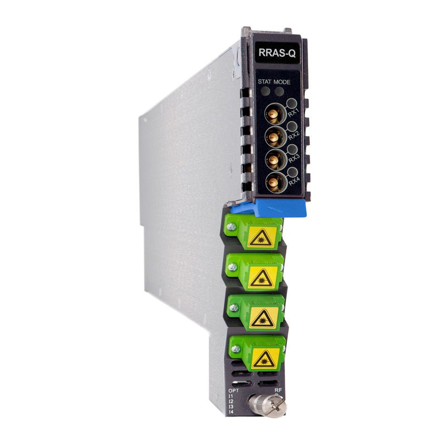
Page 25: Front Panel View
RX4 Test Point (Mini-SMB connector) Orange Tab-Retaining Clip OPT IN 1 (Optical Input 1) OPT IN 2 (Optical Input 2) OPT IN 3 (Optical Input 3) OPT IN 4 (Optical Input 4) Module Retaining Screw Technetix Group Limited Jan/2018 - V2 sales@technetix.com • technetix.com... -
Page 26: Rear Panel View
Multi-pin connector Placement Pin Notes: (1) RF1 ~ RF4 OUT connect with the blind RF connectors at the rear of the AIMA3000 chassis. (2) Redundancy connector is available for RRAR only. Technetix Group Limited Jan/2018 - V2 sales@technetix.com • technetix.com... -
Page 27: Installation
Before installing this device, you must ensure that the unit is intact and ready for installation. Unpack and check the unit: Open the box to check for any damage that may have occurred during shipment. If damage is found, please contact a Technetix customer support representative. Necessary equipment and tools for installation:... -
Page 28: Module Installation
When inserting the module into the guide rails, vertically tilt the module slightly to check that the guides are properly seated on the rails. The module is guided to the correct position using the large metal fastening screw on the lower part of the front panel. Technetix Group Limited Jan/2018 - V2 sales@technetix.com •... -
Page 29: Checking The Optical Input-Signal Level
To access the sliding fi bre guide you will need to fi rst remove the rear panel located on the back of the chassis. Unscrew the two thumbscrews on the rear panel. Technetix Group Limited Jan/2018 - V2 sales@technetix.com •... - Page 30 AIMA3000.RRAS/G/R Product User Manual Then, pull the panel forward. Then lift up the handle and slide the fi bre guide out of the front of the chassis. Technetix Group Limited Jan/2018 - V2 sales@technetix.com • technetix.com...
- Page 31 When using the sliding guide, put the fibre connector in the clip and slide it in from the rear to the front, through the chassis. Ensure that the optical fibre tail does not become trapped or pulled tightly. Fibre clip (at rear, for up to two connectors) Handle (at front) Technetix Group Limited Jan/2018 - V2 sales@technetix.com •...
-
Page 32: Using The Fibre Tray
When organising the optical fi bres, lift up the metal fl ap at the rear of the panel above the sliding guide. This will allow fi bre cables to be moved away from the sliding guide rails. Technetix Group Limited Jan/2018 - V2 sales@technetix.com... - Page 33 AIMA3000.RRAS/G/R Product User Manual Use the Fibre Guide Tool to organise the cables and wires in the fibre tray to prevent tangles and the blocking of the guide rails. Fibre Tray Area Cut-outs Technetix Group Limited Jan/2018 - V2 sales@technetix.com • technetix.com...
-
Page 34: Cleaning The Fibre Connector Ends And The Front-Panel Optical Ports
You may need to remove excess solvent using a dry lint-free swab. Alternatively, a cleaning pen such as the one click cleaner can be used. SC one click cleaning pen www.oneclickcleaner.com Technetix Group Limited Jan/2018 - V2 sales@technetix.com •... -
Page 35: Connecting The Optical Fibres
Connect the RF cables to the F-type connectors at the rear of the AIMA3000 chassis. The connectors are numbered 1 ~ 4 from top to bottom. If any RF connectors are unused, use a 75 Ω terminator to cover the port. Technetix Group Limited Jan/2018 - V2 sales@technetix.com... -
Page 36: Redundancy Connection (For Rrar Only)
At the same time, the “RX” LED indicators will also remain constant green when the signals are normal. If the optical input signal is out of the expected range, the “STAT” and “RX” LED indicator will show constant orange or red. Technetix Group Limited Jan/2018 - V2 sales@technetix.com... -
Page 37: Module Removal
A module can be removed from or inserted into the AIMA3000 chassis while power is being supplied to the AIMA3000. Always place protective dust caps on all optical connectors when not in use. Technetix Group Limited Jan/2018 - V2 sales@technetix.com •... -
Page 38: Module Configuration & Alarms
7 Module Confi guration & Alarms The module confi guration settings can be confi gured using the web interface and Technetix NMSE network management software. This manual only provides details on the web interface. For login details and network setup, please refer to the AIMA-ASMM user manual. -
Page 39: Setting Up The Rf Input Level
Monitors Optical Input Level Enable Minor Disable Enable Major AGC Status Alarm Monitors the mode for gain control Enable Minor Disable Dead Parameter Units HIHI Normal LOLO Band Input Power -18,5 -19,5 Technetix Group Limited Jan/2018 - V2 sales@technetix.com • technetix.com... - Page 40 Output Gain Type Set Automatic Gain Control or Manual Gain Control Output Gain Control Can configure attenuators to set proper RF output. Maximum 48 dBmV. Output Control Allows RF output to be toggled Technetix Group Limited Jan/2018 - V2 sales@technetix.com • technetix.com...
-
Page 41: Factory Default Settings
Output Gain Type MGC / AGC Output Gain Control 0 ~ 52 Enable Major Input Status Alarm Enable Minor Enable Major Disable Enable Major AGC Status Alarm Enable Minor Enable Major Disable Technetix Group Limited Jan/2018 - V2 sales@technetix.com • technetix.com... -
Page 42: Reboot Rras / Rrag Module
You can reboot the RRAS / RRAG module by clicking the associated “Apply” button in the “Commands” section of the RRAS / RRAG’s main confi guration page. The module’s current confi guration settings will be retained after rebooting. Technetix Group Limited Jan/2018 - V2 sales@technetix.com •... -
Page 43: Upgrade Rras / Rrag Firmware
* The web interface only supports the manual upgrades from a locally connected PC. * The RRAS / RRAG supports automated fi rmware updates and automatic backup & restore features via TFTP when managed by Technetix NMSE management software. Please refer to the NMSE Product User Manual for more information. -
Page 44: Hot-Swap Configuration
First, automatically upload the confi guration settings you want from a pre-confi gured module. Then remove the module and change the slot’s Hot-swap Mode from “Auto Upload” to “Auto Download”. Now, each new module of the same type that is inserted into this slot will automatically be confi gured with the previously uploaded settings. Technetix Group Limited Jan/2018 - V2 sales@technetix.com •... -
Page 45: Backup And Restore Feature
* The web interface only supports the manual backup and restoration of confi guration fi les from a locally connected device. * The RRAS / RRAG support automated fi rmware updates and automatic backup / restore via TFTP when managed by Technetix NMSE management software. -
Page 46: Alarm Monitoring
7.8.1 Alarm Status Pages Click the “Alarms” tab from the top menu bar to display an overview of the alarm status of all the installed modules (normal: green; alarm: red). Technetix Group Limited Jan/2018 - V2 sales@technetix.com •... - Page 47 Major Alarm: Red An individual port’s alarm status can be viewed by clicking an RRAS / RRAG’s Port Number, for example “Port 1”. This page shows input power, input status and the AGC status alarms. Technetix Group Limited Jan/2018 - V2 sales@technetix.com •...
- Page 48 AIMA3000.RRAS/G/R Product User Manual Technetix Group Limited Jan/2018 - V2 sales@technetix.com • technetix.com...
-
Page 49: Alarm Settings Configuration
You can toggle individual Temperature and Input Voltage alarms by checking or un-checking the associated boxes. Then, click on the “Submit” button to confi rm any changes. Note: Temperature and Input Voltage alarm parameters cannot be changed by the user. Technetix Group Limited Jan/2018 - V2 sales@technetix.com •... - Page 50 To display Alarm Settings for any of the RRAS / RRAG’s ports, click a port number, for example “Port 1”, on the left column of the “Modules” page. Alarm Settings Factory Default Setting (bold) Enable Major Input Status Alarm Enable Minor Disable Enable Major AGC Status Alarm Enable Minor Disable Technetix Group Limited Jan/2018 - V2 sales@technetix.com • technetix.com...
- Page 51 Click on the value of an enabled alarm you want to change, and then enter the new value. If the box next to the value is checked then the value can be changed. You can also toggle individual alarms by checking or unchecking the associated boxes. Click on the “Submit” button to confirm changes. Technetix Group Limited Jan/2018 - V2 sales@technetix.com •...
-
Page 52: Led Status Indicators
Warning Low or Warning High alarm Flashing green (1 time per second) Module operating in MGC mode Constant red: Critical Low or Critical High alarm Constant amber: Warning Low or Warning High alarm Technetix Group Limited Jan/2018 - V2 sales@technetix.com • technetix.com... - Page 53 Warning Low or Warning High alarm Constant Red: RX4 Critical Low or Critical High alarm Constant Amber: RX4 Warning Low or Warning High alarm Flashing Any Colour: Communication with remote node in progress Technetix Group Limited Jan/2018 - V2 sales@technetix.com • technetix.com...
-
Page 54: Log Management
To clear all existing events from the log, click the “Delete All” button. You must confi rm or cancel this action by clicking on the “OK” or “Cancel” button in the pop-up dialogue box. Technetix Group Limited Jan/2018 - V2 sales@technetix.com... -
Page 55: Port Configuration
“Modules” page. Port Information (read only) This page displays the Slot Number, Module Type, and Port Number. Click on the “Refresh” button to update the above information. Technetix Group Limited Jan/2018 - V2 sales@technetix.com • technetix.com... - Page 56 RF output power AGC Reference AGC reference power Configuration Parameters Factory Default Setting (bold) Input Wavelength 1310 – 1610 nm Output Control Output Gain Type Output Gain Control 42.0 (0 ~ 52 dB) Technetix Group Limited Jan/2018 - V2 sales@technetix.com • technetix.com...
-
Page 57: Optical Input Port Signal
Ensure that the diff erence between the previously measured optical input power level and the displayed RRAS / RRAG Port input level is ± 1 dBm. If not, you may need to clean the fi bre connector and optical input port. Click on the “Submit” button to confi rm any changes. Technetix Group Limited Jan/2018 - V2 sales@technetix.com •... -
Page 58: Rf Configuration
Both types of AGC modes use the current Output RF Pad Level setting in order to stabilize the output. If the RF pad level is set either too high or too low, this will affect the AGC control range. Technetix Group Limited Jan/2018 - V2 sales@technetix.com... -
Page 59: Redundancy Configuration And Alarms (For Rrar Only)
Click on ”Alarms”→”RRAR-Q”(the module name)→”Redundancy”, the redundancy alarm page will appear. In this page, you can see the redundancy alarm status of the module, and each port’s local status and confi guration status. Click on ”Refresh” to update the current alarm status. Technetix Group Limited Jan/2018 - V2 sales@technetix.com •... - Page 60 AIMA3000.RRAS/G/R Product User Manual Technetix Group Limited Jan/2018 - V2 sales@technetix.com • technetix.com...
-
Page 61: Module Application
>15dB at NPR>30dB. Figure 8-2 RRAG NPR curve Figure 8-2 RRAG NPR curve Pacific Broadband Networks 27 July 2017 Page 61 of 66 Pacific Broadband Networks 27 July 2017 Page 61 of 66 Technetix Group Limited Jan/2018 - V2 sales@technetix.com • technetix.com... -
Page 62: Common Faults
Check the optical input power; make sure it is within the normal Shows Amber low and slightly high range. If the alarm persists, contact Technetix technical support. Check the optical input power; make sure it is within the Optical Input LED Shows Red Input Port Optical Gain too Low normal range. -
Page 63: Other Faults
Replace AIMA PSU No power supply to module Damaged multi-pin connector Repair/replace module (contact Technetix support) on module Repair chassis backplane (contact Technetix support) Damaged multi-pin connector Try inserting module into a different chassis slot on chassis Incorrectly fitted module... -
Page 64: Declaration Of Conformity
According to ISO/IEC Guide 22 and EN45014 Manufacturer's Name: Technetix Manufacturer’s Address: Technetix Ltd, Innovation House, Technetix Business Park, Albourne, West Sussex, BN6 9EB Product Name: RRAS / RRAG / RRAR Analogue Return Receiver Module Series Conforms to the following standards:... - Page 65 Jan/2018 - V2...
Need help?
Do you have a question about the AIMA3000 RRAS Series and is the answer not in the manual?
Questions and answers