
Related Manuals for technetix AIMA-FRAS


Summary of Contents for technetix AIMA-FRAS
- Page 1 AIMA-FRAS OPTICAL ANALOG FORWARD RECEIVER Product user manual Online Email: customer.service.vdl@technetix.com Website: technetix.com Technetix Group Limited 2018-08/EN V1...
-
Page 2: Table Of Contents
4.1.2 Front panel layout ..................................13 4.1.3 Rear panel layout ...................................14 Installation ..................................15 5.1 Preparatory work for installation ................................15 5.2 Unpacking ........................................15 5.3 Module installation ....................................16 5.4 Connecting optical cables ..................................17 5.4.1 Using the sliding fibre guide ..............................17 2018-08/EN V1 Technetix Group Limited... - Page 3 6.6 Device upgrade ......................................39 6.7 FBC function description (only for FRAS-S-M) ..........................40 6.7.1 Spectrum ......................................40 6.7.2 QAM analyser ....................................42 6.7.3 Constellation....................................43 6.8 Redundancy configuration and alarms (only for FRAR) .........................46 Troubleshooting .................................48 7.1 Indicator for determining faults ................................48 2018-08/EN V1 Technetix Group Limited...
-
Page 4: About This Manual
Before you use the manual, please familiarise yourself with the format used in this manual. ‘*’Asterisk: Points marked with an asterisk means there is a corresponding note on the page. 1.3 Technical Support If you need help in the process of setting up and maintaining an FPAS, please contact Technetix's technical support staff: Europe:... -
Page 5: Precautions
Outage or overload requiring service and repairs Unplug the unit and refer the servicing to qualified service personnel only. Servicing and repairs DO NOT attempt to service this unit yourself. Refer all servicing needs to qualified service personnel only. 2018-08/EN V1 Technetix Group Limited... -
Page 6: Overview
Remote firmware upgrade and auto upload/download of configuration files through ASMM web interface or using the NMSE ■ Bulk firmware updates through the NMSE ■ FCC, CE and RCM compliant See Declaration of Conformity for current status. 2018-08/EN V1 Technetix Group Limited... -
Page 7: Specifications
Alarms and status Front-panel LEDS, SNMP traps Notes: Standard option. Contact a Technetix Sales Representative for availability of other options. Measured in a typical system with 0 dBm optical input, 3% - 4% OMI, and dBuV=60+dBmV. Link Performance > 53 dB >... - Page 8 45 - 1000 MHz Demodulation mode QAM64, QAM256 Metrics and functions available Level, SNR, MER, BER and live spectrum Notes: Loaded with 77 NTSC channels, measured with PBN referenced optical transmitter, 0 dBm, 3% - 4% OMI. 2018-08/EN V1 Technetix Group Limited...
-
Page 9: Block Diagram
RF TEST -20 dB -20 dB RF output test port RF DETECTOR RF sensor Full band capture BIAS Bias voltage measurement Micro-processor Module power and TO BACKPLANE AND COMMS communication interface MODULE POWER SUPPLIES Supply bus 2018-08/EN V1 Technetix Group Limited... -
Page 10: Order Details
45 - 1000 MHz (standard) 45 - 1218 MHz Notes: Option for FBC Management configurations only. Please omit X when selecting a model without FBC function. Standard option. Contact a Technetix Sales Representative for availability of other options. 2018-08/EN V1 Technetix Group Limited... -
Page 11: Frar Overview
Remote firmware upgrade and auto upload/download of configuration files through ASMM web interface or using the NMSE ■ Bulk firmware updates through the NMSE ■ Fully FCC, CE, and RCM compliant See Declaration of Conformity for current status. 2018-08/EN V1 Technetix Group Limited... -
Page 12: Specifications
Network management NMSE or through ASMM’s Web Interface Notes: Standard option. Contact a Technetix Sales Representative for availability of other options. Measured in a typical system with 0 dBm optical input, 3% - 4% OMI. dBuV=60+dBmV. Loaded with 77 NTSC channels, measured with an optical transmitter @ 0 dBm, 3% - 4% OMI. -
Page 13: Order Details
Single Optical connector type SC/APC* FC/APC LC/APC E2000/APC Bandwidth 45 - 1000 MHz (standard) 45 - 1218 MHz Notes: *Option for FBC Management configurations only. Please omit X when selecting a model without FBC function. 2018-08/EN V1 Technetix Group Limited... -
Page 14: Block Diagram
OUTPUT STAGE Post-amplifier RF OUTPUT RF output port RF TEST -20 dB -20 dB RF output test port RF DETECTOR RF sensor BIAS Bias voltage measurement Micro-processor Module power and TO BACKPLANE AND COMMS communication interface 2018-08/EN V1 Technetix Group Limited... -
Page 15: Module Characteristics
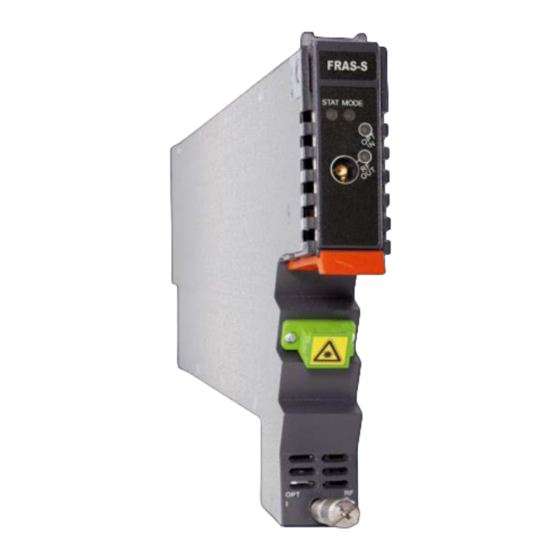
Product user manual AIMA-FRAS 4 Module characteristics 4.1 Module appearance and port layout 4.1.1 Overview Figure 4-1 module appearance 2018-08/EN V1 Technetix Group Limited... -
Page 16: Front Panel Layout
Input signal slightly high/low: Orange Input signal too high/low: Red RF output signal status indicator RF OUT ON: Green Output RF level slightly high/Low: Orange Output RF level too high/low: Red RF OUT RF output test port 2018-08/EN V1 Technetix Group Limited... -
Page 17: Rear Panel Layout
Air vent Air vent allowing air to flow out of the module Multi-pin connector Power supply and communication port Placement pin Used to position the module in the chassis Redundancy connector RF1 input test point 2018-08/EN V1 Technetix Group Limited... -
Page 18: Installation
Before installing this device, you must ensure that the unit is intact and ready for installation. Unpack and check the unit: Open the box to check for any damage that may have occurred during shipment. If damage is found, please contact a Technetix customer support representative. Necessary equipment and tools for installation:... -
Page 19: Module Installation
The module is guided to the correct position using the large position using the large metal fastening screw on the lower part of the front panel. metal fastening screw on the lower part of the front panel. 2018-08/EN V1 Technetix Group Limited... -
Page 20: Connecting Optical Cables
To access the sliding fibre guide you will need to remove the rear panel located on the back of the chassis firstly. Unscrew the two thumbscrews on the rear panel. Figure 5-3 unscrew the thumbscrews on the rear panel 2018-08/EN V1 Technetix Group Limited... - Page 21 Figure 5-5 lift up the handle and slide the fibre guide out of the front of the chassis DO NOT remove the dust cap from the fibre connector until right before connecting it to the input port. 2018-08/EN V1 Technetix Group Limited...
- Page 22 When using the sliding guide, put the fibre connector in the clip and slide it in from the rear to the front, through the chassis. Ensure that the optical fibre tail does not become trapped or pulled tightly. Fibre clip Handle (at rear, for up to two connectors) (at front) Figure 5-7 the sliding gate 2018-08/EN V1 Technetix Group Limited...
-
Page 23: Using The Fibre Tray
Figure 5-8 using the fibre tray Figure 5-9 using the fibre tray 2018-08/EN V1 Technetix Group Limited... - Page 24 Product user manual AIMA-FRAS Use the Fibre Guide Tool to organize the cables and wires in the fibre tray to prevent tangles and the blocking of the guide rails. Figure 5-10 the chassis view 2018-08/EN V1 Technetix Group Limited...
-
Page 25: Cleaning The Fibre Connector Ends And Front Panel Optical Ports
You may need to remove excess solvent using a dry lint free swab. Alternatively, a cleaning pen such as the one click cleaner can be used. SC one click cleaning pen www.oneclickcleaner.com 2018-08/EN V1 Technetix Group Limited... -
Page 26: Connecting The Optical Fibres
Insert the connector until the connector is securely held in place indicated by a clicking sound. Figure 5-12 connecting the optical fibre 5.5 Redundancy connection (for FRAR only) (a) Redundancy cable brace mounting hole on chassis (b) Redundancy cable brace (c) Redundancy cable and its brace 2018-08/EN V1 Technetix Group Limited... -
Page 27: Check Module Leds
After 15 seconds if the input signal is normal, the module STAT status LED should show a green light. The optical input indicator will show a green light. If there is no signal then the module STAT and the corresponding port status indicators will show a red light. 2018-08/EN V1 Technetix Group Limited... -
Page 28: Test The Optical Input Signal
In order to make sure the output nonlinear performance, the total output power should not be higher than 60 dBmV. CAUTION! When testing the RF signal at TP port, ensure that all unused RF ports are terminated with a 75 Ω load to reduce the potential errors during testing. 2018-08/EN V1 Technetix Group Limited... -
Page 29: Module Configuration And Alarm Setup
After logging in to the AIMA ASMM controller, select the ‘Modules’ tab and then the ‘FRAS’ to configure the FRAS module. After selecting ‘FRAS’, the ‘Port’ option will appear. Figure 6-1 module information On the FRAS main page, alarms, events and alarm settings for DC voltages can be toggled. 2018-08/EN V1 Technetix Group Limited... - Page 30 FW version firmware version Serial No FW part no firmware package number Master alarm Configuration Alarm control ON/OFF control switch Alarm setting Critical high Alarm thresholds and parameters cannot be changed Warning high Warning low Critical low Deadband 2018-08/EN V1 Technetix Group Limited...
- Page 31 To set operational mode between Manual gain control (MGC) Output gain type and Automatic gain control (AGC) Output gain control Set the output gain value Slope control RF output tilt can be set up to 7 dB slope 2018-08/EN V1 Technetix Group Limited...
- Page 32 'Alarm Settings' become available. Total Gain is calculated by adding the Input Gain Level and the Output Gain Level with 10 dB. AGC Range is from (10- 'Input Gain Control') to (0- 'Input Gain Control') 2018-08/EN V1 Technetix Group Limited...
- Page 33 Enable major alarm Enable minor Enable major Enable minor Input status alarm alarm Disable alarms Disable AGC status alarm Critical high Alarm setting Warning high Alarm level setting; Warning low Adjustable alarm parameters Critical low Deadband 2018-08/EN V1 Technetix Group Limited...
-
Page 34: Restore Factory Defaults
Slope control 0 - 7 dB 0 dB before upgrade EnableMajor Same as the configuration Input status alarm EnableMinor EnableMajor before upgrade Disable EnableMajor Same as the configuration AGC status alarm EnableMinor EnableMajor before upgrade Disable 2018-08/EN V1 Technetix Group Limited... -
Page 35: Reboot
Click the ‘Modules’ tab, select the ‘FRAS’, and then click the ‘Apply’ button next to ‘Reboot’. Next, click on ‘Submit’ to confirm, and then the module will automatically restart. The configuration of the module will be retained after rebooting. Figure 6-4 Reboot webpage 2018-08/EN V1 Technetix Group Limited... -
Page 36: Alarms Monitoring
Click the ‘Alarms’ tab on the top menu bar to display an overview of the alarm status for all the installed modules as shown in Figure 6-5. Working status alarm Normal operation: Green Major alarm: Red Figure 6-5 Alarm status page 2018-08/EN V1 Technetix Group Limited... -
Page 37: Module Operating Voltage And Temperature Alarm
Major alarm: Red Figure 6-6 Module alarm status Use the status indicators to determine if the module is working properly. If the device is replaced or reset, click on ‘Refresh’ to update the alarms information. 2018-08/EN V1 Technetix Group Limited... -
Page 38: Module Port Alarms
Click on the Module’s ‘Port’ label on the right column, as shown in Figure 6-7. The module’s optical input status, RF output power status, input status and AGC status can be viewed from this page. Figure 6-7 Module port alarms page 2018-08/EN V1 Technetix Group Limited... -
Page 39: Alarm Monitoring Configuration
Table 6-4 modules page alarms threshold parameters instruction Threshold Default Parameter Units HIHI Normal LOLO Deadband changeable Alarm by user Enable Temperature °C +12V Input 13.5 10.5 voltage +5V Input voltage Figure 6-8 alarm configuration 2018-08/EN V1 Technetix Group Limited... -
Page 40: Input/Output Status Monitoring
Critical Threshold Default Parameter Units high high Normal Deadband changeable Alarm (HIHI) (HI) (LO) (LOLO) by user Enable Optical input -5.5 power RF output dBuV 127.7 123.7 108.7 103.7 power Figure 6-9 input/output status monitoring 2018-08/EN V1 Technetix Group Limited... -
Page 41: Logs Management
The operator can view all the alarms of the modules in the chassis on the Logs Management page. Click ‘Logs’ on the top menu to enter the Logs Management page. See Figure 6-10. Figure 6-10 logs webpage 2018-08/EN V1 Technetix Group Limited... -
Page 42: Device Upgrade
* The web GUI above only supports the manual operation from a local PC. * The FRAS supports automated firmware updates and automatic backup and restore features via TFTP when managed via the NMSE management software. Please refer to the NMSE product user manual for more information. 2018-08/EN V1 Technetix Group Limited... -
Page 43: Fbc Function Description (Only For Fras-S-M)
Spectrum, QAM Analyzer and Constellation 6.7.1 Spectrum Click ‘spectrum’ on the left, open the spectrum interface, as Figure below. Figure 6-12 FRAS-S-M spectrum webpage Spectrum includes three parts: 'Spectrum', 'Select Channel' and 'Spectrum Configuration'. 2018-08/EN V1 Technetix Group Limited... - Page 44 Choose Max/Min, and then stick ‘Start’ button, 3 Spectrum Lines 3, including live, max hold and min hold curves will be shown in the spectrum. ■ Clear Max/Min: Clear the maximum hold and the minimum hold. 2018-08/EN V1 Technetix Group Limited...
-
Page 45: Qam Analyser
6.7.2 QAM analyser Click ‘QAM Analyser’ on the left, open the QAM Analyser interface, as figure 6 - 13 below. Figure 6 - 13 FRAS-S-M QAM analyser webpage Figure 6 - 14 FRAS-S-M QAM MER webpage 2018-08/EN V1 Technetix Group Limited... -
Page 46: Constellation
Backup: Click ‘Download Configuration’ to download the current channel configuration. 6.7.3 Constellation Click ‘Constellation’ on the left, open the Constellation webpage as Figure 6-16 below. ‘Constellation’ includes QAM Constellation, Select Channel, Cons Setting and QAM Result. 2018-08/EN V1 Technetix Group Limited... - Page 47 FBCM module factory defaults and reboot. Factory default settings and Reboot can be operated from the main FRAS-S-M page FBCM commands. You can apply the factory default configuration and reboot the FBCM module by clicking the associated ‘Apply’ button. 2018-08/EN V1 Technetix Group Limited...
- Page 48 If more than one user has access to the webpage, it may make the spectrum capture incomplete, Please press the ‘start’ button if you see the incomplete spectrum. When using the FBC function, it recommended that the RF output power of the main port is no less than 90 dBuV/ch. 2018-08/EN V1 Technetix Group Limited...
-
Page 49: Redundancy Configuration And Alarms (Only For Frar)
In the box of ‘Port Redundancy Information’, you can enable or disable each port’s redundancy, set their local status alarm level and configure the alarm level individually. ■ Please click on ‘Submit’ to save your configurations whenever you make changes to the settings. 2018-08/EN V1 Technetix Group Limited... - Page 50 In this page, you can see the redundancy alarm status of the module, and each port’s local status and configuration status. Click on ‘Refresh’ to update the current alarm status. Figure 6-19 FRAR redundancy alarm webpage 2018-08/EN V1 Technetix Group Limited...
-
Page 51: Troubleshooting
If this fault still exists when the input optical power is normal, contact Technetix Technical Support Staff. Input optical power abnormal Bias current abnormal, contact Technetix Technical Support Staff. Power failure Contact Technetix Technical Support Staff. STAT is Red Reduce the room temperature.
Need help?
Do you have a question about the AIMA-FRAS and is the answer not in the manual?
Questions and answers