
Related Manuals for technetix AIMA3000


Summary of Contents for technetix AIMA3000
- Page 1 AIMA3000 Advanced Intelligent Multi-Service Headend Platform Product User Manual May/2016 - Version 1.0...
- Page 2 AIMA3000 Chassis Product User Manual AIMA3000 Advanced Intelligent Multi-Service Headend Platform Product User Manual Technetix Group Limited May/2016 - Version 1.0 sales@technetix.com • technetix.com...
-
Page 3: Table Of Contents
AIMA3000 Chassis Product User Manual Contents About This Manual ..............................5 Chapter Overview ....................................5 Related Documentation ..................................5 Technical Support ....................................6 Precautions .................................7 Overview ..................................8 About the Product ....................................8 3.2 Typical Application ....................................8 3.3 Features ........................................8 3.4 Specifications ......................................9 3.5 Order Details ......................................11 Chassis Characteristics ............................12... - Page 4 AIMA3000 Chassis Product User Manual Chassis Installation ....................................21 4.7.1 Initial Checks ....................................21 4.7.2 Assembling the Chassis ................................21 4.7.3 Installing the Chassis ..................................27 4.7.4 Connecting the chassis ground ..............................27 4.7.5 Connecting the Chassis Electrical Supplies .........................27 4.7.6 Performing a Power-on Test ...............................27 4.7.7...
-
Page 5: About This Manual
Technetix.AIMA3000 - Product User Manual • Technetix.AIMA ASMM - Product User Manual • AIMA3000 NMS Web Management System Product User Manual Technetix.NMS3-EPSM - Basic Inventory Management Technetix.NMS3-EPSM - Basic Alarm Management Technetix.NMS3-EPSM - Basic System Management Technetix.NMS3-EPSM - Basic Template Management Technetix Group Limited May/2016 - Version 1.0... -
Page 6: Technical Support
‘*’ Asterisk: Points marked with an asterisk means there is a corresponding note on the page 1.4 Technical Support If you need help in the process of setting up and maintaining an AIMA3000, please contact Technetix’s technical support staff: Europe:... -
Page 7: Precautions
Outage or overload requiring service and repairs Unplug the unit and refer only to Technetix qualified service personnel. Servicing and repairs Do not attempt to service this unit yourself. Refer all servicing needs to Technetix qualified service personnel only. WARNING! Exposure to class 1M laser radiation is possible. -
Page 8: Overview
While FTTx technologies are making their way into traditional cable MSO networks, the AIMA3000 supports a range of RFoG modules such as the RRAG to ease the transition to full-blown PON/ P2P. For networks with FTTx technologies already in place, delivering high speed data and voice services, the AIMA3000 is geared to provide a full-spectrum CATV overlay using transmitters and EDFA modules. -
Page 9: Specifications
3.4 Specifications Chassis (ACHA) Module slots 17 slots for AIMA3000 plug-and-play modules. Slot 0 is used for the System Management Module (ASMM). Slots 1~16 are used for any of the Application Modules. Alarms Requires an ASMM module in slot 0. - Page 10 Storage humidity Max. 90% RH (non-condensing) Cooling Cooling fans in the power supply modules and the 8 fan units mounted in the chassis. Multiple AIMA3000 chassis can be mounted on top of each other without needing ventilation space. Dimensions Overall width 482.6 mm (including flanges)
-
Page 11: Order Details
3.5 Order Details AIMA3000 Chassis A-ACHA-4U AIMA3000 Chassis, 4RU, 16+1 slots, 19 inch, fans included, power supply not included A-APSA-460-XX Power Supply Module with fan for mains 90~260 Vac 50/60 Hz, 460 W. XX: AU, CN, CH, EU, UK, US... -
Page 12: Chassis Characteristics
AIMA3000 Chassis Product User Manual 4 Chassis Characteristics 4.1 Chassis Appearance 4.1.1 Overview Module fastening screw Chassis front Lifting handles Technetix Group Limited May/2016 - Version 1.0 sales@technetix.com • technetix.com... -
Page 13: Front Chassis View
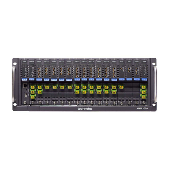
AIMA3000 Chassis Product User Manual 4.1.2 Front Chassis View Item Description ASMM module in slot 0 Various application modules in slots 0 ~ 16 Lifting handles (2) Rack mounting holes (4) Sliding fibre guide (to feed optical cables through from rear of chassis) -
Page 14: Rear Chassis View
AIMA3000 Chassis Product User Manual 4.1.3 Rear Chassis View Item Description Chassis grounding terminal Chassis RF connectors Redundancy cable connector location Power supply modules (up to 2) Fibre tray cover Fan module cover (8 individual fans are installed) RF panel (4 RF connectors on 1 panel) Technetix Group Limited May/2016 - Version 1.0... -
Page 15: Chassis Components
AIMA3000 Chassis Product User Manual 4.2 Chassis Components The packaged chassis includes a fan module and two power supply modules, which are described below. 4.2.1 Fan Module The fan module comprises eight individual fans, powered in parallel; a single fan failure does not affect the other fans. The ASMM system management module monitors the rotational speed of each fan. -
Page 16: Power Supply Modules
AIMA3000 Chassis Product User Manual 4.2.2 Power Supply Modules AIMA3000 power supply modules are hot swappable and support load balancing. Up to two power supplies can be used in the same chassis, and are available in different configurations: • AC power supply module, input voltage of 90 ~ 260 Vac (50/60 Hz) •... -
Page 17: Ac Power Supply
AIMA3000 Chassis Product User Manual 4.2.3 AC Power Supply Front panel view for AC power supply Item Description External power-input connector Status LED: Green – normal operation; Red – alarm condition Fan unit cover Fan unit (supports hot-swapping) Power supply module securing screws... -
Page 18: Dc Power Supply
AIMA3000 Chassis Product User Manual 4.2.4 DC Power Supply Front panel view for DC power supply Item Description External power-input connector Status LED: Green – normal operation; Red – alarm condition Fan unit cover Fan unit (supports hot-swapping) Fan unit power connector... -
Page 19: Equipment Inventory
The power supply module feeds the chassis power bus, which in turn provides power to each of the module slots. The AIMA3000 is designed for operating between -5 °C ~ +55 °C. Fans in the power supply module and in the separate fan module cool the chassis. -
Page 20: Installation Overview
AIMA3000 Chassis Product User Manual 4.6 Installation Overview 4.6.1 Tools required You will need a Phillips head screwdriver to secure the screws. 4.6.2 Installation sequence To install the AIMA3000 chassis: 1. Unpack and inspect the chassis components 2. Assemble the chassis... -
Page 21: Chassis Installation
4.7.2.1 Removing the transit brace The AIMA3000 chassis is supplied with an internal transit brace fitted, which must be removed before you attempt to assemble any other parts. Remove the 4 screws that secure the transit brace to the chassis, and then remove the transit brace from the chassis. - Page 22 AIMA3000 Chassis Product User Manual 4.7.2.2 Attaching the fibre tray and the chassis lifting handles Fibre tray securing screws (4) Lifting handle securing screws (6 each side) Use four M3 screws to secure the fibre tray to the chassis front.
- Page 23 To remove the fan module, unfasten the 4 securing screws and carefully withdraw the fan module from the rear of the chassis. CAUTION! If you need to remove the fan module while the AIMA3000 chassis is operating, ensure that you refit or replace the fan module with minimum delay, to avoid overheating and possible damage to the equipment.
- Page 24 AIMA3000 Chassis Product User Manual 4.7.2.4 Installing and removing fan units Each fan unit has 2 securing screws To install a fan unit, first insert the white cable connector into the correct socket in the fan module body, at the left-hand side of the fan unit’s location.
- Page 25 AIMA3000 Chassis Product User Manual 4.7.2.5 Installing and removing power supply modules Securing screw Use the handle on the power supply module To install a power supply module, align it squarely with the recess in the chassis and then use the handle to slide the module in until the module’s PCB connector engages with the chassis connector.
- Page 26 AIMA3000 Chassis Product User Manual 4.7.2.6 Removing and installing a power supply fan unit Endplate screws (2) Endplate screws (2) To remove the power supply fan unit, first disconnect the white cable connector from the FAN socket in the module.
-
Page 27: Installing The Chassis
The AIMA3000 is designed to be installed in a standard 19-inch rack, which must be of good quality and robust construction due to the heavy weight of a fully populated AIMA3000 chassis. Slide rails or a support tray in the rack is recommended. -
Page 28: Installing The System Management Module And Application Modules
AIMA Module Orange retaining clip Hold the AIMA module casing upright, align it with the AIMA3000 slide rails for the correct slot and insert the module until it reaches the multi-pin connector. DO NOT use excessive force when inserting the module, but ensure the RF connectors at the rear of the module are securely connected with the chassis's RF connectors. -
Page 29: Connecting Optical Cables
Only use fingers to fasten the mounting screw. DO NOT use a screwdriver. 4.8 Connecting Optical Cables For the convenience of the user, the AIMA3000 Chassis has a Sliding Fibre Guide to help the operator to arrange the cables. 4.8.1 Using the Sliding Fibre Guide The sliding fibre guide is located in the lower-left corner of the chassis if looking at the front of the chassis and is designed to help installation of the optical fibre cabling. - Page 30 AIMA3000 Chassis Product User Manual Then, pull the panel forward. Then lift up the handle and slide the fibre guide out of the front of the chassis. Technetix Group Limited May/2016 - Version 1.0 sales@technetix.com • technetix.com...
- Page 31 AIMA3000 Chassis Product User Manual DO NOT remove the dust cap from the fibre connector until right before connecting it to the input port. Raise the clip, insert the fibre connector and then lower the clip over the connector. When using the sliding guide, put the fibre connector in the clip and slide it in from the rear to the front, through the chassis.
-
Page 32: Using The Fibre Tray
AIMA3000 Chassis Product User Manual 4.8.2 Using the Fibre Tray All optical fibres must be organised in a tidy manner in the chassis’s fibre tray, which provides enough space for up to 64 optical fibres. This allows for easy positioning and future replacement of optical fibres. Along the front of the chassis, there are cut-outs for keeping the optical fibres in position. - Page 33 AIMA3000 Chassis Product User Manual Use the Fibre Guide Tool to organise the cables and wires in the fibre tray to prevent tangles and the blocking of the guide rails. Fibre Tray Area Cut-outs Technetix Group Limited May/2016 - Version 1.0 sales@technetix.com...
-
Page 34: Cleaning The Fibre Connector Ends And Front-Panel Optical Ports
AIMA3000 Chassis Product User Manual 4.8.3 Cleaning the Fibre Connector Ends and Front-panel Optical Ports To obtain a good quality optical input signal, optical fibre input ports and fibre connector ends must be carefully cleaned. Connection terminal Head face When cleaning the optical fibre-connector end, remove the dust cap and then use a lint-free cloth dampened with a static dissipative solvent to clean the angled surface. -
Page 35: Connecting The Optical Fibres
AIMA3000 Chassis Product User Manual 4.8.4 Connecting the Optical Fibres Carefully lift up the hinged cover of the optical input port, align the raised tab on the connector with the slot in the port. Insert the connector until the connector is securely held in place indicated by a clicking sound. -
Page 36: Chassis Configuration & Alarms
5.1.2 Configuration using an Android device The Android application may not be compatible with all Android devices. The app was developed by Technetix to be used in conjunction with a Lenovo Ideapad A1 07 running Android 2.3.4 Gingerbread. Before installing the application, the installation of unknown sources must be enabled by going to settings ->... - Page 37 AIMA3000 Chassis Product User Manual a. Get to Android settings. Select “More Settings” in “Wireless and Network” settings and select “Tethering and portable hotspot” and “USB tethering”. After selecting USB Tether, the indicator “tethered” needs to show up. Note: The operator should connect a USB cable to Android device again after each time the module or computer is reset.
- Page 38 AIMA3000 Chassis Product User Manual Note: The default IP of ASMM is 192.168.42.1 because the default IP of Android system is 192.168.42.129 usually. Technetix Group Limited May/2016 - Version 1.0 sales@technetix.com • technetix.com...
-
Page 39: Alarm Monitoring
AIMA3000 Chassis Product User Manual 5.2 Alarm Monitoring The fan module and power supply support alarm monitoring and management via the ASMM system management module. 5.2.1 Fan Module Alarms related to the fan module depend on the relationship between an individual fan unit's speed, current, and temperature. - Page 40 AIMA3000 Chassis Product User Manual Click "Refresh" to update the information. Alarm Settings Configuration Click the "Modules" tab on the top menu bar. Click "AFAN" in the left column of the "Modules" page. Technetix Group Limited May/2016 - Version 1.0 sales@technetix.com...
-
Page 41: Power Supply Modules
AIMA3000 Chassis Product User Manual Module Information (read only) Click "Refresh" to update the information. Configuration • Alarm Control (Enable / Disable) • Unit Alarm Enable (Enable Major / Enable Minor / Disable) Choose the settings from the drop-down menus, and then click "Submit" to confirm changes. - Page 42 AIMA3000 Chassis Product User Manual Click "Refresh" to update the information. Alarm Settings Configuration Click the "Modules" tab on the top menu bar. Click "PS1" or "PS2" in the left column of the "Modules" page. Module Information (read only) Model, Serial No., HW Assembly No., FW Part No., FW Version Click "Refresh"...
-
Page 43: Log Management
AIMA3000 Chassis Product User Manual Threshold Default Alarm Parameter Units HIHI Normal LOLO DeadBand changeable by Enable user Temperature °C +12V Input voltage 13,5 10,5 +5V Input voltage -5V Input voltage -4,3 5.3 Log Management Click the "Logs" tab on the top menu bar to display an event history (up to 1000 events) of all recorded alarms for all the installed modules. -
Page 44: Troubleshooting
LED Status Common Fault Possible Solution One power supply LED Abnormal power output Repair / replace power supply module (contact Technetix support) shows red. from power supply module Both power supply LEDs Application module Locate the faulty application module (remove modules until the power... -
Page 45: Declaration Of Conformity
Technetix Ltd, Innovation House, Technetix Business Park, Albourne, West Sussex, BN6 9EB Declares, that the product Product Name: AIMA3000 – Advanced Intelligent Multi-services Access Platform Conforms to the following standards: Safety: EN 80083-1, EN 60950, IEC 950, AS/NZS 3260:1993, EN-60825-1, IEC 825-1, AS/NZS 2211.1 Laser Safety... -
Page 46: Appendix A: Factory Default Settings
AIMA3000 Chassis Product User Manual Appendix A: Factory Default Settings Name Option Factory Default Alarm Control Enable / Disable Enable Unit Alarm Enable Enable Major / Enable Minor / Disable Enable Major Alarm Enable (Fan Units #1 ~ #8) Enable Major / Enable Minor / Disable... -
Page 47: Appendix B: Default Alarm Limit Settings
AIMA3000 Chassis Product User Manual Appendix B: Factory Default Settings Power Supply Modules Threshold Dead Default Alarm Parameter Units HIHI Normal LOLO changeable Band Enable by user Temperature °C +12V Input voltage 13,5 10,5 +5V Input voltage -5V Input voltage... - Page 48 May/2016 - Version 1.0...
Need help?
Do you have a question about the AIMA3000 and is the answer not in the manual?
Questions and answers