Table of Contents
Advertisement
Quick Links
OPERATING MANUAL
F F A A N N T T O O M
3
Edition:
FARMET a.s.
phone: +420 491 450 111
Jiřinková 276
fax: +420 491 450 136
552 03 Česká Skalice, CZ
GSM: +420 774 715 738
FANTOM
F F X X 4 4 7 7 0 0 N N S S
F F X X 4 4 7 7 0 0 N N S S
1.1.2018
Effective from:
M
www.farmet.cz
IČ: 46504931
e-mail: farmet@farmet.cz
DIĆ: CZ46504931
Advertisement
Table of Contents

Related Manuals for Farmet FANTOM FX 470 NS


Summary of Contents for Farmet FANTOM FX 470 NS
- Page 1 F F X X 4 4 7 7 0 0 N N S S F F X X 4 4 7 7 0 0 N N S S 1.1.2018 Edition: Effective from: FARMET a.s. phone: +420 491 450 111 www.farmet.cz IČ: 46504931 Jiřinková 276 fax: +420 491 450 136 e-mail: farmet@farmet.cz...
- Page 2 Prepared by: Technical Department, Farmet a.s. on 24.4.2019, changes reserved 2 | 37...
-
Page 3: Preface
PREFACE Dear customer, The agricultural machine you have purchased is a high-quality product of Farmet a.s. Česká Skalice. You can fully utilise the advantages of your machine after thoroughly studying the operating manual. The serial number of the machine is punched on the production label and written in the operating manual (Your Machine Characteristics). - Page 4 PREFACE IMPORTANT READ CAREFULLY BEFORE USE KEEP FOR FUTURE REFERENCE 4 | 37...
-
Page 5: Table Of Contents
PREFACE Contents PREFACE ..........................3 1 MACHINE LIMIT PARAMETERS . - Page 6 PREFACE 6 | 37...
-
Page 7: Machine Limit Parameters
Transport of persons and animals on the machine structure, Transport of burdens on the machine structure, Aggregation of the machine with another towing equipment than stated in Chapter „8.1“. 1.1 Technical parameters PARAMETERS FANTOM FX 470 NS 4,68 m Working width Transport width Transport height... -
Page 8: General Instructions For Use
GENERAL INSTRUCTIONS FOR USE 2 GENERAL INSTRUCTIONS FOR USE The machine is made in accordance with the latest equipment state and approved safety • regulations. However, dangers of user or third person injury or machine damage or creation of other material damage may arise during use. Use the machine only in a technically sound condition, in accordance with its purpose, •... - Page 9 GENERAL INSTRUCTIONS FOR USE The operator must not consume alcohol, medicines, narcotic and hallucinogenic • substances that decrease his attention and coordination capabilities while using the machine. If the operator must use medicines prescribed by a physician or uses freely sold medicines, he must be informed by a physician, whether he is capable of responsible and safe operation of the machine under these circumstances.
-
Page 10: Machine Transport Using Transport Means
MACHINE TRANSPORT USING TRANSPORT MEANS 3 MACHINE TRANSPORT USING TRANSPORT MEANS • The transport means designed for machine transport must have the load capacity minimally identical with the weight of the transported machine. The total weight of the machine is stated on the production label. -
Page 11: Machine Handling Using Lifting Equipment
MACHINE HANDLING USING LIFTING EQUIPMENT 4 MACHINE HANDLING USING LIFTING EQUIPMENT The lifting equipment and tying means designed for handling of the machine must have their • load capacity at least identical with the weight of the handled machine. Machine fastening for handling may only be performed in places designed for that and •... -
Page 12: Work Safety Labels
WORK SAFETY LABELS 5 WORK SAFETY LABELS Warning safety labels serve for operator protection. General: • Strictly observe the warning safety labels. • All safety instructions also apply to other users. • Upon damage or destruction of the aforementioned "SAFETY LABEL" located on the machine, THE OPERATOR IS OBLIGED TO REPLACE IT WITH A NEW ONE!!! •... - Page 13 WORK SAFETY LABELS Travelling and transport on the machine P 37 H structure is strictly forbidden. When working and transporting the P 39 H machine, maintain safe distance from the electric appliances The pressure vessel is under gas and oil P 42 H pressure.
- Page 14 WORK SAFETY LABELS Fig. 1 - Location of safety labels on the machine FANTOM FX 470 NS 14 | 37...
-
Page 15: Description
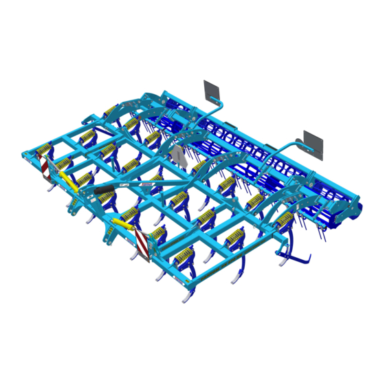
6 DESCRIPTION The machine FANTOM FX 470 NS is structurally solved as carried. It is equipped with a three-point hitch, TBZ 3. It consists of a central frame and two folding side frames where the tines with chisels in three rows. -
Page 16: Machine Assembly At The Customer
MACHINE ASSEMBLY AT THE CUSTOMER 7 MACHINE ASSEMBLY AT THE CUSTOMER • The operator must perform the assembly according to the instructions of the producer, best in cooperation with the expert servicing technician determined by the producer. • The operator must secure a functional test of all assembled parts after the completion of the machine assembly. -
Page 17: Commissioning
COMMISSIONING 8 COMMISSIONING • Before taking over the machine, test and check, whether damage occurred during transport and whether all parts contained in the bill of delivery were supplied. • Before commissioning the machine, carefully read this operating manual, especially Chapters 1–5. -
Page 18: Agregation To A Tractor
The table of requirements for the towing means for work with the machine: Requirement for the tractor engine power for the machine > 160 kW * FANTOM FX 470 NS Spacing of the lower suspension 895 ± 1,5 mm joints (measured at the joint axes) 1100 ±... -
Page 19: Folding And Unfolding Of The Machine
COMMISSIONING 8.3 Folding and unfolding of the machine • With all hydraulic movements, lower the speed of the moving parts of the machine before stopping by throttling the corresponding valve at the control unit! • The hydraulics for the folding and unfolding must be connected to the double-action control unit. -
Page 20: Description Of The Share/Chisel Replacement
COMMISSIONING 8.4 Description of the share/chisel replacement • If the ploughshare / chisel wear is high, this working tool must be replaced • Tools required for replacement: • HAMMER • DRIVER - 12 mm • The installation is the same for all types of working parts The machine is sufficiently lifted so that the working part can be removed from the... -
Page 21: Rear Accessories
REAR ACCESSORIES 9 REAR ACCESSORIES Various types of rollers can be installed on the machine: • Tube roller TR: Diameter 500 mm Weight 90 kg/m • Ring roller RR: Diameter 520 mm Weight 160 kg/m • V-Ring roller VR: Diameter 580 mm Weight 175 kg/m •... - Page 22 REAR ACCESSORIES Diameter 400/350 mm Weight 120 kg/m • Disk roller SDR: Diameter 580 mm Weight 220 kg/m Roller Crumbling ●●○○ ●●●○ ●●●○ ●●●○ ●●●○ Stamping ●●●○ ●●●● ●●●● ●●●○ ●●●● Depth guiding ●●●○ ●●●● ●●●● ●●●● ●●●● Resistance against clogging ●○○○...
-
Page 23: Setting Levelling
REAR ACCESSORIES 9.1 Setting levelling 9.1.1 Setting the angle of rear levelling Set levelling according to the current soil conditions with regard to the wear condition of the levelling rods. A – Using the rear pin, set the required height of the levelling rods – set the pin at the same position in all 6 points. -
Page 24: Machine Transport On Roads
MACHINE TRANSPORT ON ROADS 10 MACHINE TRANSPORT ON ROADS Transport position of FANTOM FX 470 NS • Connect the machine by suspending on the tractor using the three-point suspension equipment . • Lower the side frameworks in the transport position. -
Page 25: Machine Adjustment
MACHINE ADJUSTMENT 11 MACHINE ADJUSTMENT Only adjust the machine when it is resting on the shares, e.g. when it is recessed (see below). Set the longitudinal plane of the machine by positioning the lower arms of the tractor and by adjusting the drawbar of the tractor third point to secure the same depth of processing for the first, second and third row of the shares. -
Page 26: Adjusting The Working Depth Of The Machine
• Set the working depth of the machine using the top pin in the slot link of the rear frame of the roller according to Tab. 5. To release the pin, lift the machine in the tractor arms a bit. Tab.5 FANTOM FX 470 NS Top pin Approximate... - Page 27 MACHINE ADJUSTMENT Setting the working depth using piston rods • The working depth of the machine is set by various combinations of the spacers on the piston rods of the rollers. • The individual combination of spacers for the required depth of the machine are stated in Tab. 6 •...
- Page 28 MACHINE ADJUSTMENT 1. Lift the machine, attached to the tractor, and lower the rollers down to the maximum low position us- ing the piston rods (piston rods are drawn out). Set the required number of spacers on the piston rods of the rollers.
-
Page 29: Setting Side Deflectors
MACHINE ADJUSTMENT 11.2 Setting side deflectors • The deflector height needs to be set at various levels according to the type of soil and crop residue quantity (see the picture below). • Setting the distance of the deflector blade from the edge part. 29 | 37... -
Page 30: Share Securing
MACHINE ADJUSTMENT 11.3 Share securing The shares are protected against overload by compression springs that do not require any other adjustment. Pos. Title Compression spring Spring pin Connecting rod Bolt Top share with deflector Chisel 50 MULTICARBIDE PRO Chisel 50 MULTICARBIDE V-plough 30 | 37... -
Page 31: Machine Maintenance And Repairs
MACHINE MAINTENANCE AND REPAIRS 12 MACHINE MAINTENANCE AND REPAIRS Observe the safety instructions for treatment and maintenance. • If it is necessary to weld during the repair and have the machine connected to the tractor, it must have disconnected supply cables from the alternator and the accumulator. •... -
Page 32: Machine Storage
MACHINE STORAGE 13 MACHINE STORAGE Long-term machine shutdown: • Store the machine under a roof if possible. • Store the machine on a flat and solid surface with sufficient load capacity. • Clean the machine before storing and conserve so that it is not damaged in any way during storage. -
Page 33: Machine Lubrication Schedule
MACHINE LUBRICATION SCHEDULE 14 MACHINE LUBRICATION SCHEDULE • The machine is completely maintenance free when it comes to lubrication. Therefore, it is not necessary to lubricate the machine. 33 | 37... -
Page 34: Enviromental Protection
ENVIROMENTAL PROTECTION 15 ENVIROMENTAL PROTECTION • Regularly check the tightness of the hydraulic system. • Preventively replace or repair hydraulic hoses, possibly further parts of the hydraulic system showing signs of damage, before oil leaks occur. • Check the condition of hydraulic hoses and perform their timely replacement. The service life of hydraulic hoses includes the time, when they were stored. -
Page 35: Machine Disposal After Service Life Expiry
MACHINE DISPOSAL AFTER SERVICE LIFE EXPIRY 16 MACHINE DISPOSAL AFTER SERVICE LIFE EXPIRY • The operator must secure during machine disposal that steel parts and parts, in which hydraulic oil or lubricating grease moves are differentiated. • Steel parts must be cut by the operator while observing safety regulations and handed over to the secondary raw material collection point. -
Page 36: Servicing And Warranty Conditions
6. The warranty is limited to the disassembly and assembly, possibly replacement or repair of the defective part. The decision, whether to replace or repair the defective part, is up to the contractual workshop of Farmet. 7. During the warranty period, only the authorised servicing technician of the manufacturer may perform repairs or other interventions into the machine. - Page 37 SERVICING AND WARRANTY CONDITIONS 37 | 37...