Table of Contents
Advertisement
Quick Links
Ohmic Instruments
Phone (410) 820-5111
Toll Free(800) 626-7713
3081 Elm Point Industrial Drive
St. Charles, MO 63301 USA
Fax (410) 822-9633
www.ohmicinstruments.com
Sales: sales@ohmicinstruments.com
Service: service@ohmicinstruments.com
DPSC-35XR(L) MANUAL
DEW POINT SIGNAL
CONDITIONER KIT
SF-SLS-553 (A)
1
Advertisement
Table of Contents

Related Manuals for Ohmic instruments DPSC-35XR


Summary of Contents for Ohmic instruments DPSC-35XR
- Page 1 Ohmic Instruments Phone (410) 820-5111 Toll Free(800) 626-7713 3081 Elm Point Industrial Drive St. Charles, MO 63301 USA Fax (410) 822-9633 www.ohmicinstruments.com Sales: sales@ohmicinstruments.com Service: service@ohmicinstruments.com DPSC-35XR(L) MANUAL DEW POINT SIGNAL CONDITIONER KIT SF-SLS-553 (A)
- Page 2 © Ohmic Instruments 2014...
-
Page 3: Table Of Contents
Contents Introduction ....................4 Features ....................4 Installation ....................5 Operation ....................6 RS-232 Interface ..................6 Recalibration ..................... 7 Special Order .................... 8 Mounting Template ................... 9 Wiring Diagram ..................10 Alarm Reset Wiring ................. 11 Analog Output Table ................12 Sensor Precautions ................. -
Page 4: Introduction
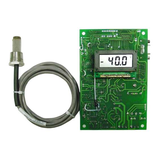
INTRODUCTION tioning Engineers) and referenced to the Hyland-Wexler equations Ohmic’s Dew Point Signal Condi- used by NIST. The DPSC-35XR tioner Kit, Model DPSC-35XR (and provides rapid response to changes DPSC-35XRL, the time-stamp log- in the amount of water vapor with a... -
Page 5: Installation
INSTALLATION relay is normally open “dry” contact which closes when the dew point CAUTION: The DPSC-35XR is exceeds the set point. powered by 120 VAC. When pow- ered, the unit has several live ter- Place selector switch S2 in the de- minals exposed. -
Page 6: Operation
Oil mist forms a vapor barri- Connecting to a serial port The er over the sensor which slows re- DPSC-35XR can be plugged into any sponse time. (When used on a des- 9-pin PC serial (COM) port using a 9-... -
Page 7: Recalibration
Communications Program Communications Commands All commands are in upper-case The DPSC-35XR transmits data via characters (set your CAPS LOCK its RS-232 output as soon as it is on). n indicates where a number powered up. In order to receive the... -
Page 8: Special Order
35XR’s for service and recali- bration, be sure to include the corresponding probes. SPECIAL ORDER For a nominal fee, the DPSC-35XR can be retrofitted by Ohmic with ei- ther or both of these options: 24 Volt: The DPSC-35XR can be modified so it will operate from a 24 volt DC source instead of AC. -
Page 9: Mounting Template
Figure 1 DPSC-35XR Mounting Template (Template drawing is to be used on installation side of enclosure) -
Page 10: Wiring Diagram
Figure 2 Card Wiring Diagram... -
Page 11: Alarm Reset Wiring
Figure 3 Alarm Reset Wiring For user connection to reset an mally closed pushbutton switch alarm device, see the illustration across terminals 3 and 4. Retain above. The 470 ohm resistor is on the supplied jumper across 1 and 2. the PC board as shipped. -
Page 12: Analog Output Table
F/C-DP V-out I-out F/C-DP V-out I-out F/C-DP V-out I-out F/C-DP V-out I-out 0.000 4.000 1.259 8.030 2.519 12.059 3.778 16.089 0.037 4.119 1.296 8.148 2.556 12.178 3.815 16.207 0.074 4.237 1.333 8.267 2.593 12.296 3.852 16.326 0.111 4.356 1.370 8.385 2.630 12.415 3.889 16.444 0.148... -
Page 13: Sensor Precautions
III. Max. Pressure: 175 psi IV. Electrical: Never connect the sensor probe to any other device; the signal conditioning circuitry in the DPSC-35XR is specific to the sensor. Connecting the sensor to other circuitry or meters (including multi- meters) can cause damage to the sensor. -
Page 14: Logging Commands (Logging Version Only)
LOGGING COMMANDS FOR LOG- 3. The following commands apply to the GER VERSION ONLY (DPSC-35XRL) logger version (DPSC-35XRL) only: S<Enter> Transmits current settings 1. When the unit is powered up, the of parameters: C#, L#, N# computer’s screen will display the (C is autotransmit data in following: seconds, L is logging rate... -
Page 15: Warranty
If any failure occurs, the following steps should Or call Ohmic Technical Support at 410-820-5111. be taken: 1. Notify Ohmic Instruments giving full details of the All rights reserved. This manual may not be repro- difficulty, and include the model, type, and serial duced in full or in part without written permission of numbers (where applicable).
Need help?
Do you have a question about the DPSC-35XR and is the answer not in the manual?
Questions and answers