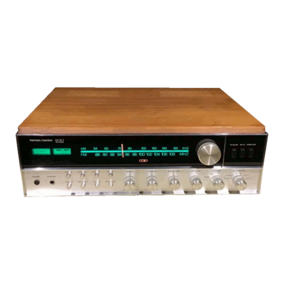
Summary of Contents for Harman Kardon 930
- Page 1 The Harman-Kardon Model 930 AM/FM/Stereo FM Solid State Receiver Instruction Manual harman/kardon T H E M U S I C C O M P A N Y...
- Page 2 You now are the owner of an instrument unique in conception, design and manufacture. For example, the two separate power supplies of the 930 (one for each channel) guarantees flawless performance regardless of how much power the amplifiers are called on to deliver.
-
Page 3: Warranty And Service Policy
WARRANTY and SERVICE POLICY POLICY This warranty is not applicable to any instrument which shall have been repaired We warrant each unit to be free from defects in material and workmanship or altered in any way so as, in our judgment, to affect its stability or reliability under normal use and service, and in accordance with the conditions set forth or has been subject to neglect, misuse, abuse, negligence, or accident;... -
Page 4: Installation Procedure
INSTALLATION PROCEDURE SPEAKER PHASING VENTILATION When more than one speaker is used in a music reproducing system, the Although your new Receiver rarely develops high heat, it is still recommend speakers must be connected in a manner which will allow them to work together. ed that you leave the back of the cabinet open. - Page 5 Your two speakers should be identical, if possible, to obtain optimum results. Experts agree that a perfectly matched system offers the best stereo phonic reproduction. The speakers should be placed along the same wall ap proximately 8 to 10 feet apart depending upon room s i z e and furniture place ment, It may be necessary to experiment with speaker placement until best results are obtained.
- Page 6 CONNECTING THE SPEAKERS FOR STEREO OPERATION (2 SYSTEMS) 1, Connect all four speakers for two system operation as shown in Dia If your receiver is to be used monophonically and stereo is to be added gram. at a later date, it is essential that both speaker output terminals are terminated info a proper load to prevent damage to the output stage of the receiver.
- Page 7 CONNECTING THE SPEAKER FOR STEREOPHONIC OPERATION (SYSTEM 1} AND MONOPHONIC OPERATION (SYSTEM 2} If your receiver is to be used monophonically and stereo is to be added at a later date, if is essential that both speaker output terminals are terminated into a proper load to prevent damage to the output stage of the receiver.
-
Page 8: Input Connections
INPUT CONNECTIONS This special convenience permits you to connect a record changer and a CONNECTING the FM ANTENNA manual turntable simultaneously, and to switch between them with the function The antenna input has been designed to accept either a 300 ohm balanced selector located on the front panel. - Page 9 MODEL 930 REAR PANEL DIAGRAM STEREO STEREO RECORD TAPE PLAYER RECORDER LOOPSTICK ANTENNA GROUND SCREW ANTENNA PREAMP "OUT" SPEAKER SPEAKER SPEAKER AUXILIARY TERMINAL MAIN AMP "IN" SYSTEM I SYSTEM 2 FUSES AC POWER STRIP RECEPTACLES FUSE CORD LERMINAL STRIP FERMINAL STRIP...
- Page 10 MODEL 930 FRONT PANEL DIAGRAM STEREO FUNCTION SIGNAL AM DIAL FM DIAL TUNING MUTING FILTER AUTO INDICATOR STRENGTH BALANCE KNOB SCALE SCALE SWITCH SWITCH SWITCH LIGHTS METER METER MODE TONE TAPE ILLUMINATED BALANCE LOW-CUT BASS SPKR-I SELECTOR MON-2 DEFEAT POWER...
-
Page 11: Operating Procedure
OPERATING PROCEDURE Every control on this receiver serves ci specific useful function and is MODE SWITCH important for the proper operation of your stereo system. The MODE switch selects between stereophonic and monophonic operation We recommend that you read the following section carefully so you may depending upon the program source. - Page 12 SPEAKER SYSTEM SELECTOR SWITCHES CONTOUR SWITCH One of the limitations of human hearing is its tendency to lose sensitivity Your receiver has been provided with two independent speaker selector to the very low pitched sounds as the program sound level is reduced. It is this switches.
- Page 13 EQUALIZATION STEREO INDICATOR A stereo indicator is located directly behind the dial glass and operates In order to achieve good reproduction of the wide range of frequencies in conjunction with the FM position of the Function switch and the Stereo Auto in music and to make necessary adjustment for the limitations of the recording “IN”...


Need help?
Do you have a question about the 930 and is the answer not in the manual?
Questions and answers