Table of Contents
Advertisement
Manual
®
Series DMA
O O M M 1 1 7 7 0 0
Integrated Amplifiers
PROFESSIONAL AUDIO & SOUND
Installation Manual
and Operating Instructions
4 Channel - 2 Zone - VOX - Mute -
MOH - Phone Interface
D D M M A A 2 2 0 0 1 1 5 5 - - 1 1 5 5 W W a a t t t t R R M M S S
D D M M A A 2 2 0 0 3 3 0 0 - - 3 3 0 0 W W a a t t t t R R M M S S
D D M M A A 2 2 0 0 6 6 0 0 - - 6 6 0 0 W W a a t t t t R R M M S S
D D M M A A 2 2 1 1 2 2 0 0 - - 1 1 2 2 0 0 W W a a t t t t R R M M S S
IMPORTANT NOTE: THIS OPERATING MANUAL IS PROVIDED AS AN INSTALLATION AND
AS AN OPERATING AID. PASO SOUND PRODUCTS, INC. DOES NOT ASSUME ANY
RESPONSIBILITY AS TO ITS ACCURACY AND SHALL NOT BE LIABLE IN TORT OR CON-
TRACT FOR ANY DIRECT CONSEQUENTIAL OR INCIDENTAL LOSS OR DAMAGE ARISING
FROM THE INSTALLATION, USE OR INABILITY TO USE THIS PRODUCT.
LISTED
T T O O R R E E D D U U C C E E T T H H E E R R I I S S K K O O F F F F I I R R E E O O R R E E L L E E C C T T R R I I C C
COMMERCIAL
AUDIO
EQUIPMENT
CAUTION !
S S H H O O C C K K D D O O N N O O T T E E X X P P O O S S E E T T H H I I S S A A P P P P L L I I A A N N C C E E T T O O
30TJ
W W A A T T E E R R , , R R A A I I N N O O R R M M O O I I S S T T U U R R E E
Innovation through technology since 1931
REV. 1.5
© copyright Paso Sound Products, Inc. 2005
Specifications are subject to change without notice
Advertisement
Table of Contents

Subscribe to Our Youtube Channel
Related Manuals for Paso Sound Products DMA2015


Summary of Contents for Paso Sound Products DMA2015
- Page 1 Manual ® Series DMA O O M M 1 1 7 7 0 0 Integrated Amplifiers PROFESSIONAL AUDIO & SOUND Installation Manual and Operating Instructions 4 Channel - 2 Zone - VOX - Mute - MOH - Phone Interface D D M M A A 2 2 0 0 1 1 5 5 - - 1 1 5 5 W W a a t t t t R R M M S S D D M M A A 2 2 0 0 3 3 0 0 - - 3 3 0 0 W W a a t t t t R R M M S S D D M M A A 2 2 0 0 6 6 0 0 - - 6 6 0 0 W W a a t t t t R R M M S S D D M M A A 2 2 1 1 2 2 0 0 - - 1 1 2 2 0 0 W W a a t t t t R R M M S S...
- Page 2 Power Surge, Overload and Thermal Protection Power Requirement: 117 Volt, 50-60 hZ Power Consumption: DMA2015 = AC = 570 VA - DMA2030 = 600 VA DMA2060 = 670VA - DMA2120 = 850VA Max. AC Accessory Outlet: 117 v - 500 W Max. Unswitched...
- Page 3 B) Turn amplifier up side down and remove the four rubber feet by unscrewing the four holding screws. C) Remove the bottom front screws on each side of the amplifier holding the amplifier cover. D) Install the rack kit brackets by using the self-tapping screws provided. DMA2015/2030/2060/2120 outlet, consult an electrician for replacement of the obsolete outlet.
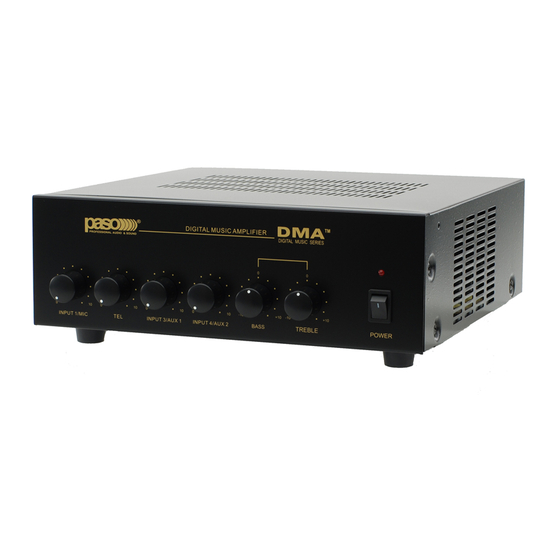
- Page 4 INPUT 4/AUX 2 Volume Control PAGE 4 SPECIFICATIONS ARE SUBJECT TO CHANGE WITHOUT NOTICE Fig. 4 - FRONT PANEL CONTROLS DIGITAL MUSIC AMPLIFIER INPUT 3/AUX 1 INPUT 4/AUX 2 BASS Control TREBLE Control On-Off Power Switch DIGITAL MUSIC SERIES POWER BASS TREBLE DMA2015/2030/2060/2120...
-
Page 5: Rear Panel Inputs/Outputs/Controls
15W RMS MUTE DELAY SENS 3 - 60 SEC DMA2015 Rear Panel Manual INPUT 4 - AUX 2 - Stereo Summing Jacks INPUT 3 - AUX 1 - Stereo Summing Jacks INPUT 3 - AUX 1 Input Attenuator TONE BYPASS - ON/OFF SWITCH... -
Page 6: Maun And Preamplifter Board Top View
FUNCTION SWITCHES AND JUMPERS LOCATION S115 S110 AUX1 (INPUT S109 PAGE 6 PHANTOM (MIC S104 S105 (MIC S103 (MIC S102 S108 (INPUT S113 (INPUT S114 (INPUT S112 SPECIFICATIONS ARE SUBJECT TO CHANGE WITHOUT NOTICE OFF M1 S204 S203 OFF V1 DMA2015/2030/2060/2120... - Page 7 INPUT 3 - S107 MOH/ZONE 1 INPUT SOURCE AUX 1 - AUX 2 S201 EQ LINK S202 TONE BYPASS DMA2015/2030/2060/2120 FUNCTION DESCRIPTION PHANTOM POWER ON - OFF PHANTOM POWER ON - OFF PHANTOM POWER ON - OFF VOX 1 - OFF...
- Page 8 SPECIFICATIONS ARE SUBJECT TO CHANGE WITHOUT NOTICE SETTING THE VOX AND MUTE JUMPERS VOX JUMPERS MUTE JUMPERS SOCKET SOCKET S113 S114 OFF M1 OFF V1 Fig. 8A - VOX and MUTE Sockets IMPORTANT NOTE OFF, and V1 OFF, and M1 JUMPER DMA2015/2030/2060/2120...
- Page 9 SIGNAL PRESENT ON THE S111 MUTE 1 BUSS WILL MUTE THE MUSIC FROM INPUT DMA Input 1- 3 - 4 - 03 MUTE RECEIVE DMA2015/2030/2060/2120 FUNCTION SETTINGS EXAMPLES VOX 1 BUSS ON JUMPER MUTE 1 BUSS OFF VOX 1 BUSS OFF...
- Page 10 Do not route cable near or over Fluorescent Fixtures. Do not route cable next to Speaker Wires. Do not install cable inside Power Line Conduits. DMA Micunbal 01 Avoid the use of staples that may penetrate the cable. DMA2015/2030/2060/2120 Microphone...
- Page 11 Connect Muting Switch to MUTE 1 and G Terminals. If using the VOX system (Voice Activated) the muting switch is unnecessary. DMA2015/2030/2060/2120 INSTALLATION AND WIRING CAUTION: TO PREVENT POSSIBLE DAMAGE TO SPEAKERS OR THE AMPLIFIER ALL INPUT CONNECTIONS MUST BE MADE WITH THE AMPLIFIER POWER OFF.
- Page 12 INPUT 4 S101 INPUT 1- 3 - 4 DEFAULT JUMPER SETTINGS INPUT 1 (MIC) G COM HOT Input Jumper No. INPUT 1 S104 INPUT 3 S103 INPUT 4 S102 -0 +18V +18V DMA2015/2030/2060/2120 AUX 1 AUX 2 Setting DMA2015 Micbal Electret...
- Page 13 MUTE any Input with the MUTE 1 Setting SWITCHED ON. G COM HOT 600 ohm 100 mV BALANCED NOTE: To change the INPUT Default Settings refer to the appropriate section in this Manual DMA2015 Telpaging 01 PAGE 13...
- Page 14 Fig. 14 - Rear Panel AUX 1 Input Diagram INPUT - 3 (AUX1) 47 kohm 100 mV AUX 1 ATTENUATOR DMA2015 Stereo Summ AUX 1 Fig. 14A - Stereo Summing and AUX 1 Input Attenuator PAGE 14 SPECIFICATIONS ARE SUBJECT TO CHANGE WITHOUT NOTICE INSTALLATION AND WIRING JUMPERS/SWITCH NO.
-
Page 15: Setting Input 4 As Aux 2
SWITCH MUSIC OUTPUT Fig. 15 - Rear Panel AUX 2 Input Diagram INPUT 4 (AUX 2) 47 Kohm 100 mV DMA2015 Stereo Summ AUX 2 Fig. 15A - Stereo Summing and AUX 2 Input Attenuator DMA2015/2030/2060/2120 INSTALLATION AND WIRING S108... - Page 16 VOX1 - OFF SPECIFICATIONS ARE SUBJECT TO CHANGE WITHOUT NOTICE VOX SENSITIVITY CONTROLS MUTE DELAY SENS 3-30 SEC DMA2015 Vox Sens 01 Fig. 16 - Rear Panel VOX 1 Sensitivity Control and MUTE Time Delay Control VOX SENSITIVITY ADJUSTMENT FACTORY SETTING DMA2015/2030/2060/2120...
- Page 17 MUTE 1 - OFF MUTE 1 - OFF MUTE 1 - OFF SPECIFICATIONS ARE SUBJECT TO CHANGE WITHOUT NOTICE DIRECT MUTING WIRING 24V DC MUTE 250 MA DELAY 3-6- SEC MUTING SWITCH M 1 DMA2015 M1 01 FACTORY FACTORY SETTING SETTING PAGE 17...
- Page 18 Lo Z 2 - ZONE PAGING SELECTORS SPST ZONE ZONE 1 ZONE 2 SWITCHES PAGING MICROPHONE DMA2015 2 Zone Diagram 01 Fig. 18B - 2 - Zone Switching Panel DMA2015/2030/2060/2120 diagram below 250ohm 1.5mV BALANCED A = Common B = Hot...
- Page 19 ® DIGITAL MUSIC AMPLIFIERS PROFESSIONAL AUDIO & SOUND INSTALLATION AND WIRING Fig. 19 - 2 Zone Paging and Music System 2 ZONE PAGING AND MUSIC WIRING DIAGRAM (SHIELD) GROUND COMMON PAGE 19 DMA2015/2030/2060/2120 SPECIFICATIONS ARE SUBJECT TO CHANGE WITHOUT NOTICE...
- Page 20 LINE OUT Fig. 20B - Rear Panel Mix Buss Bridging Diagram PAGE 20 INSTALLATION AND WIRING paso TONE BYPASS DMA2015 EQlink MIX BUSS BRIDGING AMPLIFIER B BUSS LINE OUT DMA2015 Mixbuss SPECIFICATIONS ARE SUBJECT TO CHANGE WITHOUT NOTICE EXTERNAL EQUALIZER LINK...
- Page 21 VOLUME INPUT 3 (AUX 1) REMOTE VOLUME CONTROL 10 K ohm POTENTIOMETER DMA2015 Remote Volume Fig. 21B - Input 3 Remote Volume Control Diagram REMOTE VOLUME CONTROL - OPTIONAL ACCESSORY RVC10W Front View RVC10W Rear View REGULATED AUXILIARY POWER SUPPLY 8 OHM 2 Watt Max.
- Page 22 Attach Silver Label packed with module 24 V DC 8 OHM 250 MA 2 Watt Max. DMA2015 15W RMS DMA2015 Rear Panel Manual PAGE 22 SPECIFICATIONS ARE SUBJECT TO CHANGE WITHOUT NOTICE TOP COVER PMEQ32B DIGITAL MUSIC AMPLIFIER DIGITAL MUSIC SERIES...
- Page 23 CHIME CARD SOCKET CHIME ACTIVATION SWITCH 24 V DC 250 MA 8 OHM 2 Watt Max. DMA2015 15W RMS DMA2015 Chime Activation Fig. 23A - AC1B/DMS Wiring Diagram DMA2015/2030/2060/2120 OPTIONAL CHIME CARD SOCKET CN 209 CHIME MODULE AMPLIFIER REAR PANEL...
- Page 24 4) Muting activation of M1 or M2 Buss (from Microphones or Telephone) does not effect the Output of the MOH/ZONE 1. SPECIFICATIONS ARE SUBJECT TO CHANGE WITHOUT NOTICE MOH - ZONE 1 INPUT SOURCE DEFAULT JUMPER SETTING S107 AUX1 AUX2 DMA2015 MOH 01 DMA2015/2030/2060/2120...
- Page 25 4) Set Jumper as required (AUX 1 or AUX 2) 5) Replace protective cover. SPECIFICATIONS ARE SUBJECT TO CHANGE WITHOUT NOTICE MOH - ZONE 1 INPUT SOURCE DEFAULT JUMPER DMA2015 15W RMS AUX1 MUTE DELAY SENS 3 - 60 SEC DMA2015 MOH Zone 1 SETTING S107 AUX2 PAGE 25...
- Page 26 8) Level Control on the rear panel to the desired output level. SPECIFICATIONS ARE SUBJECT TO CHANGE WITHOUT NOTICE 24 V DC 250 MA DMA2015 15W RMS MUTE DELAY SENS 3 - 60 SEC DMA2015 Zone 1 ZONE 1 OUTPUT LEVEL CONTROL ZONE 1 SETTINGS DMA2015/2030/2060/2120...
- Page 27 Output Power to Zone 1 each Speaker is 1 Watt MOH OUT 2 WATT BALANCED DMA2015 ZONE 1 SPKR 02 Fig 27A - Using two 4 or 8 ohm Speakers 8 ohm 8 ohm 1/2 W 1/2 W Maximum Output...
- Page 28 Speakers SPK 3 and SPK 4 are not affected. NOTE: The total power required for all the speaker or speakers to be controlled should not exceed the Power Handling rating of the Attenuator. Example: the maximum load for the VC20 is 20 Watt. DMA2015/2030/2060/2120...
- Page 29 Jukebox is cycling between CD’s it is possible that the Music Source (Background Music) may cut-in causing annoying and unwanted chatter while the Jukebox is still active. To prevent this problem the MUTE TIME DELAY TRIMMER should be adjusted accordingly. DMA2015/2030/2060/2120 OPTIONAL MUSIC ONLY ZONE JUKEBOX...
- Page 30 Microphone or the Telephone) turn the VOX SENS Control slowly clockwise until the Music is muted. NOTE: The Paging from the Microphone or the Telephone will NOT be routed to the the MOH Output. SPECIFICATIONS ARE SUBJECT TO CHANGE WITHOUT NOTICE DMA2015/2030/2060/2120...
- Page 31 ® DIGITAL MUSIC AMPLIFIERS PROFESSIONAL AUDIO & SOUND SATELLITE RECEIVER MUSIC AND MESSAGES ON HOLD WIRING DIAGRAM System Telephone DMA2015/2030/2060/2120 SPECIFICATIONS ARE SUBJECT TO CHANGE WITHOUT NOTICE PAGE 31...
- Page 32 ® DIGITAL MUSIC AMPLIFIERS PROFESSIONAL AUDIO & SOUND REPLACEMENT PARTS REPLACEMENT PARTS Please provide complete information when you request replace- ment parts from either the Factory or a Paso Authorized Distributor. Be certain to include the Part Number and Description as it appears on the parts list, the Model Number of the unit and if possible the Serial Number and the date of pur- chase of the unit.
Need help?
Do you have a question about the DMA2015 and is the answer not in the manual?
Questions and answers