
Related Manuals for Force Computers SPARC CPU-54

Summary of Contents for Force Computers SPARC CPU-54
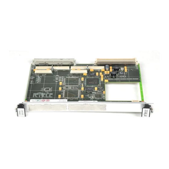
- Page 1 (217) 352-9330 | Click HERE Find the Emerson / Motorola / Force Computers CPU-54T at our website:...
- Page 2 SPARC/CPU-54 Reference Guide P/N 220991 Revision AA May 2003...
- Page 3 Force Computers, GmbH. Force Computers, GmbH assumes no responsibility for the use of any circuitry other than circuitry that is part of a product of Force Computers, GmbH.
- Page 4 Headquarters The Americas Europe Asia Force Computers Inc. Force Computers GmbH Force Computers Japan KK 4211 Starboard Drive Lilienthalstr. 15 Shibadaimon MF Building 4F Fremont, CA 94538 D-85579 Neubiberg/München 2-1-16 Shiba Daimon U.S.A.
-
Page 6: Table Of Contents
Contents Using This Guide Other Sources of Information Safety Notes Sicherheitshinweise Introduction Features ............1-3 CPU . - Page 7 Ordering Information ..........1-9 Product Nomenclature .
- Page 8 Controls, Indicators, and Connectors Front Panel of the SPARC/CPU-54 ........3-3 LEDs .
- Page 9 Displaying System Information ........4-19 Ethernet Address and Host ID .
- Page 10 Switch 4 and 5 Status Register ........... . . 5-17 Switch 800 Status Register .
- Page 11 SPARC/CPU-54...
- Page 12 Tables Introduction Table 1 Standard Compliance..........1-8 Table 2 Product Nomenclature .
- Page 13 OpenBoot Firmware Table 19 Boot Parameters ........... . 4-7 Table 20 Device Alias Definitions for SCSI#1 .
- Page 14 Figures Introduction Figure 1 Function Blocks ........... . . 1-3 Figure 2 Block Diagram of the CPU Board .
- Page 15 OpenBoot Firmware Figure 18 System Overview ........... 4-4 Figure 19 OBDIAG Main Menu .
-
Page 16: Using This Guide
Using This Guide This Reference Guide is intended for users qualified in electronics or electri- cal engineering. Users must have a working understanding of Peripheral Component Interconnect (PCI), VMEbus, and telecommunications. Conventions Notation Description 1234 All numbers are decimal numbers except when used with the nota- tions described below 00000000 Typical notation for hexadecimal numbers (digits are 0 through F),... - Page 17 Revision History Order Revision Date Description 212466 February 2001 Preliminary Installation Guide 21466 May 2001 Corrected “Expansion” page -xxi; Removed interfaces section in chapter 1; Removed block diagram of I/O board, infor- mation on I/O-board installation, connector pinouts of I/O-board and created separate Installation Guide for I/O-board;...
- Page 18 Order Revision Date Description 212466 May 2001 Corrected pinout 19 and 62 in Figure 14 “68- Pin Ultra-Wide SCSI Connector Pinout” page 3-10; Corrected Table 18 “On-Board Connectors” page 3-11 and Table 19 “P2 Backplane Con- nector Signals” page 3-11; Corrected pinout row Z in Figure 15 “P2 VMEbus Connector Pinout Rows Z-B”...
- Page 19 Order Revision Date Description 216116 June 2002 Modified “Safety Notes” page xxi and “Sicherheitshinweise” page xxv; modified Figure 2 “Block Diagram of the CPU Board” page 1-5; replaced EN 50081/2 with EN 55022/4 in Table 1 “Standard Compliance” page 1-8; modified and updated section “Ordering Information”...
- Page 20 Order Revision Date Description 220991 May 2003 Corrected pinout of RS-422 interface Added information on termination when using RS-422 interfaces SPARC/CPU-54...
-
Page 21: Other Sources Of Information
Other Sources of Information For further information refer to the following documents: Company www. Document Force Computers forcecomputers.com SPARC/CPU-54 OpenBoot Enhancements Programmer’s Guide (P/N 216134) SPARC/IO-54 Installation Guide (P/N 214901) SPARC/IOBP-54 Installation Guide (P/N 213170) SPARC/MEM-54 Installation Guide (P/N 214000) IEEE Standards ieee.com... -
Page 22: Safety Notes
The board has been tested in a standard Force Computers system and found to comply with the limits for a Class A digital device in this sys- tem, pursuant to part 15 of the FCC Rules, EN 55022 Class A respectively. - Page 23 Installation Electrostatic discharge and incorrect board installation and removal can damage circuits or shorten their life. Therefore: • Before installing or removing the board, read the “Action Plan” sec- tion page 2-3. • Before touching boards or electronic components, make sure that you are working in an ESD-safe environment.
- Page 24 Replacement/Expansion Only replace or expand components or system parts with those recom- mended by Force Computers. Otherwise, you are fully responsible for the impact on EMC and the possibly changed functionality of the prod- uct. Check the total power consumption of all components installed (see the technical specification of the respective components).
- Page 25 Battery If a lithium battery on the board has to be exchanged, observe the follow- ing safety notes: • Exchanging the battery always results in data loss of the devices which use the battery as power backup. Therefore, backup affected data before exchanging the battery.
-
Page 26: Sicherheitshinweise
Sicherheitsvorschriften und darf ausschließlich für Anwendungen in der Telekommunikationsindustrie und im Zusammenhang mit Industriesteuerungen verwendet werden. Einbau, Wartung und Betrieb dürfen nur von durch Force Computers ausgebildetem oder im Bereich Elektronik oder Elektrotechnik qualifiziertem Personal durchgeführt werden. Die in diesem Handbuch enthaltenen Informationen dienen ausschließlich dazu, das Wissen von... - Page 27 Wenn Sie das Board ohne ein PMC Modul verwenden, schirmen Sie freie Steckplätze mit einer Blende ab, um einen ausreichenden EMV Schutz zu gewährleisten. Wenn Sie Boards in Systeme einbauen, schirmen Sie freie Steckplätze mit einer Blende ab. Installation Elektrostatische Entladung und unsachgemäßer Ein- und Ausbau des Boards kann Schaltkreise beschädigen oder ihre Lebensdauer verkürzen.
- Page 28 Betrieb Achten Sie darauf, dass die Umgebungs- und die Leistungsanforderungen während des Betriebs eingehalten werden. Betreiben Sie das SPARC/CPU-54 nur innerhalb der angegebenen Gren- zwerte für die relative Luftfeuchtigkeit und Temperatur, da durch hohe Luftfeuchtigkeit und Kondensation Kurzschlüsse entstehen können. Stellen Sie vor dem Einschalten des Stroms sicher, dass sich auf dem SPARC/CPU-54 kein Kondensat befindet, und betreiben Sie das SPARC/CPU-54 nicht unter 0°C.
- Page 29 RJ-45 Stecker Das CPU Board ist mit RJ-45 Steckern ausgestattet. Dieser Stecker wird sowohl für Telefonanschlüsse als auch für Netzwerkkabel (Twisted Pair Ethernet - TPE) verwendet. Die Verwechslung dieser Anschlüsse kann sowohl das Telefon als auch das Board zerstören. Beachten Sie deshalb die folgenden Punkte: •...
-
Page 30: Introduction
Introduction... -
Page 32: Features
Introduction Features Features The SPARC/CPU-54 is the successor of the SPARC/CPU-50. It is a sin- gle-board computer with a processor frequency of 500 MHz and is designed in the 6U VMEbus form factor. It includes a PCI bus sub- system with 32-bit/33 MHz. On-board are: •... -
Page 33: Cpu
Features Introduction The UltraSPARC-IIe CPU with 500 MHz has sensors for observing the CPU on-die temperature and provides the following features: • Four-way superscalar processor • SPARC V9 Architecture with the VIS instruction set • 64-bit data path and 44-bit address pointers •... -
Page 34: Block Diagram
Introduction Block Diagram Block Diagram The block diagram shows how the devices of the SPARC/CPU-54 work together and which data paths they use. Block Diagram of the CPU Board Figure 2: SPARC/CPU-54 1 - 5... -
Page 35: Cpu Board Variants
CPU Board Variants Introduction CPU Board Variants The SPARC/CPU-54 is available as CPU board and also in combination with the I/O-54. If combined with the I/O-54, the SPARC/CPU-54 is called SPARC/CPU-54T and allows the installation of PMC modules. SPARC/CPU-54 The SPARC/CPU-54 consists of a single-slot CPU board. Figure 3: SPARC/CPU-54 1 - 6... -
Page 36: Sparc/Cpu-54T
Introduction CPU Board Variants SPARC/CPU-54T The SPARC/CPU-54T consists of a single-slot CPU board and a single- slot I/O-54, which allows to mount two PMC modules. For further information on the I/O board, refer to the IO-54 Installation Guide. SPARC/CPU-54T Figure 4: SPARC/CPU-54 1 - 7... -
Page 37: Standard Compliance
Standard Compliance Introduction Standard Compliance The CPU board was designed to comply with the standards listed below. Note: The board is not compliant to EN 55022 if you connect a SCSI device to the SCSI connector on the front panel. Table 1: Standard Compliance Standard... -
Page 38: Ordering Information
Introduction Ordering Information Ordering Information When ordering board variants, upgrades, and accessories, use the order numbers given below. Product Nomenclature In the following table you find the key for the product name extensions. Table 2: Product Nomenclature SPARC/CPU-54(T)/mmm-sss-c-uu SDRAM capacity in MByte CPU speed in MHz L2-cache User flash EPROM size in MByte... -
Page 39: Order Numbers
Ordering Information Introduction Order Numbers The table below is an excerpt from the board’s ordering information. Ask your local Force Computers representative for the current SPARC/CPU-54 ordering information. Table 3: Excerpt from the SPARC/CPU-54 Ordering Information for CPU Boards Order No. -
Page 40: Table 5 Excerpt From The Sparc/Cpu-54 Ordering Information For Accessories
Introduction Ordering Information Table 5: Excerpt from the SPARC/CPU-54 Ordering Information for Accessories Order No. SPARC/... Description 108771 IOBP-54/3 3-row I/O panel for the CPU-54 and I/O-54 with 3-row P2 connector pinout 108772 IOBP-54/5 5-row I/O panel for the CPU-54 and I/O-54 with 5-row P2 connector pinout 108773 .../CPU-54/AccKit/3... - Page 41 Ordering Information Introduction 1 - 12 SPARC/CPU-54...
-
Page 42: Installation
Installation... -
Page 44: Action Plan
Installation Action Plan Action Plan In order to install the board, the following steps are necessary and will be described in further detail in the sections of this chapter. SPARC/CPU-54 2 - 3... -
Page 45: Requirements
Requirements Installation Requirements In order to meet the environmental requirements, the CPU board has to be tested in the system in which it is to be installed. Before you power up the board, calculate the power needed according to your combination of board upgrades and accessories. Environmental Requirements The environmental conditions must be tested and proven in the used system configuration. -
Page 46: Power Consumption
SPARC/CPU-54 vari- ant. For information on the accessories’ power consumption, refer to the documentation delivered together with the respective accessory or con- sult your local Force Computers representative for further details. The installation of the SPARC/CPU-54 requires: • +5V power supply •... -
Page 47: Table 7 Maximum Power Consumption
Requirements Installation The power supply has to meet the requirements given in the tables be- low. Table 7: Maximum Power Consumption CPU Board +12V Major Components SPARC/CPU-54/ 4.5A n.a. CPU-54 400 MHz, 128 MByte 128-400-1-4 SDRAM SPARC/CPU-54/ 5.0A n.a. CPU-54 500 MHz, 512 MByte 512-500-1-4 SDRAM SPARC/CPU-54T/... -
Page 48: Software Requirements
Installation Requirements Software Requirements If you wish to use one of the SPARC/CPU-54 devices listed below you need to install the Force Computers Solaris Driver Package Version 2.11 or higher: • Intel 82559 Ethernet device • Universe II PCI-to-VMEbus bridge •... -
Page 49: Hardware And Software Upgrades And Accessories
Hardware and Software Upgrades and Accessories Installation Hardware and Software Upgrades and Accessories The following upgrades and accessories are available for the SPARC/CPU-54: • SPARC/MEM-54 memory module • IO-54 • IOBP-54 • Solaris Driver Package Memory Modules The main memory capacity is adjustable via installation of the Force Computers memory module SPARC/MEM-54. -
Page 50: Sparc/Iobp-54
SW5-2 on the CPU board must be configured appropriately to dis- able the corresponding backplane SCSI termination. Solaris Driver Package Force Computers provides a Solaris driver package which supports the following devices and features of the SPARC/CPU-54: • Intel 82559 Ethernet device •... -
Page 51: Setting The Scsi Termination
Setting the SCSI Termination Installation Setting the SCSI Termination The SPARC/CPU-54 provides two Ultra Wide SCSI buses. SCSI 1 is accessible via the front panel and the backplane via the IOBP-54. SCSI 2 is available via the backplane via the IOBP-54. The SPARC/CPU-54 enables and disables the SCSI termination automatically according to the board’s position in the SCSI bus, if switch SW5 is set to the respec- tive default settings. -
Page 52: Figure 5 Scsi Termination Concept Of Sparc/Cpu-54 And Iobp-54
Installation Setting the SCSI Termination The figure below shows the SCSI bus termination concept on the SPARC/CPU-54 and the IOBP-54. Figure 5: SCSI Termination Concept of SPARC/CPU-54 and IOBP-54 SPARC/CPU-54 2 - 11... -
Page 53: Switch Settings
Switch Settings Installation Switch Settings Caution The switch settings have to be checked and changed before the board installation. Do not set/reset the switches during operation. Other- wise, the board is damaged. The SPARC/CPU-54 provides five configuration switches: SW4, SW5, SW6, SW7, and SW800. - Page 54 Installation Switch Settings The switches SW5 and SW800 are located on the bottom side of the board. Figure 7: Location of Switches on Board’s Bottom Side Table 9: Switch Settings Switch Description Abort key control OFF (default): ABORT key enabled ON: ABORT key disabled Reset key on front panel control OFF (default): RESET key enabled...
- Page 55 Switch Settings Installation Table 9: Switch Settings (cont.) Switch Description Termination for SCSI 1 on front panel OFF (default): Front panel termination automatic ON: Front panel termination disabled Termination for SCSI 1 on P2 OFF (default): Manual termination enabled ON: Manual termination disabled Automatic termination for SCSI 1 on P2 OFF: Automatic termination disabled ON (default): Automatic termination enabled...
- Page 56 Installation Switch Settings Table 9: Switch Settings (cont.) Switch Description SW800 Automatic VMEbus slot-1 detection OFF (default): Automatic detection of VMEbus slot-1 function ON: Automatic detection of VMEbus slot-1 function disabled. Set SW800-2 appropriately. Manual VMEbus slot-1 selection - only relevant if SW800-1 is ON OFF (default): VMEbus slot-1 function enabled ON: VMEbus slot-1 function disabled...
-
Page 57: Board Installation
Board Installation Installation Board Installation The SPARC/CPU-54 can be installed in a system with or without the IO-54. Caution The SPARC/CPU-54 has to be installed in a non-powered system. If you install the SPARC/CPU-54 in or remove it from a powered sys- tem, the system board and other cards installed may be damaged. -
Page 58: Installing The Cpu Board
Installation Board Installation Caution If more than one system controller is active in the VMEbus system, the board or other VMEbus participants can be damaged. Therefore, always ensure that only one CPU board is configured to be system controller in the VMEbus system. Installing the CPU Board 1. -
Page 59: Powering Up
Board Installation Installation Powering Up We recommend to use a terminal when powering up the SPARC/CPU-54. The advantage of using a terminal is that you do not need any frame buffer, monitor, or keyboard for initial powering up. Note: • Before powering up, check the “Requirements” section on page 2- 4 for installation prerequisites and requirements. -
Page 60: Installing Solaris
Installation Board Installation Installing Solaris The SPARC/CPU-54 is designed to run with Solaris Version 8 10/00 or higher with the 64-bit kernel. Pay attention to the guidelines in this sec- tion before and during Solaris installation. Note: • Solaris versions prior to version 8 10/00 are not supported. SPARC/CPU-54 runs with 64-bit kernel only. -
Page 61: Solaris 8
Board Installation Installation Solaris 8 When setting up Solaris interactively, these packages can be installed by selecting/deselecting the proper software group in the software dialog window. If applicable, customize the software group as shown in the following table. Table 10: Customizing Solaris 8 Software Group Customizing Entire distribution plus OEM support... -
Page 62: Solaris Driver Package
Installation Board Installation Solaris Driver Package The following table shows which driver has to be installed for a particu- lar device. Table 12: Devices and Their Appropriate Drivers Device Driver Name Intel 82559 Ethernet controller FRCiprb Universe II PCI-to-VMEbus bridge FRCvme On-board flash memory FRCflash... -
Page 63: Table 13 Hardware Node Assignment
Board Installation Installation The following table shows how the hardware node names are assigned to a label on the front panel and the IOBP. Table 13: Hardware Node Assignment Label Location Hardware Node ETHERNET1 CPU front panel /pci@1f,0/network@1,1 (standard Solaris hme Ethernet device) ETHERNET2 CPU IOBP /pci@1f,0/pci@3/ethernet@1... -
Page 64: Table 15 Flash Segmentation And Write Protection
Installation Board Installation FRCflash The Solaris 2.x flash memory driver provides access to the flash EPROM device. According to the SPARC/CPU-54(T) switch settings, the flash EPROM is accessible as one user flash or is divided into a boot and a user section. - Page 65 Board Installation Installation 2 - 24 SPARC/CPU-54...
-
Page 66: Controls, Indicators, And Connectors
Controls, Indicators, and Connectors... -
Page 68: Front Panel Of The Sparc/Cpu-54
Controls, Indicators, and Connectors Front Panel of the SPARC/CPU-54 Front Panel of the SPARC/CPU-54 The following figure shows the connectors, keys and LEDs available on the front panel of the SPARC/CPU-54. For the front panel features of the IO-54, see the IO-54 Installation Guide. Figure 8: SPARC/CPU-54 Front Panel SPARC/CPU-54... -
Page 69: Leds
Front Panel of the SPARC/CPU-54 Controls, Indicators, and Connectors LEDs The figure below shows the LEDs available on the SPARC/CPU-54. Figure 9: Front Panel LEDs Table 16: Description of Front Panel LEDs Description DIAG Software-programmable hexadecimal display for diagnostics CPU status LED Green: Normal operation Red: Processor halted or reset is active;... -
Page 70: Keys
Controls, Indicators, and Connectors Front Panel of the SPARC/CPU-54 Keys The front panel of the SPARC/CPU-54 provides two mechanical keys and a hexadecimal rotary switch (front panel shows MODE). Reset When enabled and toggled, it instantaneously affects the CPU board by generating a push-button Power On Reset (POR) to the UltraSPARC-IIe. -
Page 71: Connectors
Front Panel of the SPARC/CPU-54 Controls, Indicators, and Connectors Connectors By means of the front panel connectors, the peripherals can be con- nected to the SPARC/CPU-54. Ethernet Two full duplex Ethernet interfaces are available at the front panel via the 10BaseT/100BaseTx Twisted-Pair-Ethernet (TPE) connectors. Figure 10: Twisted-Pair Ethernet Connector Pinout The Ethernet #1 interface is also accessible at the 5-row P2 back panel connector. -
Page 72: Serial I/O
Controls, Indicators, and Connectors Front Panel of the SPARC/CPU-54 Serial I/O The serial interface on the CPU board’s front panel holds the signals for the two serial interfaces A and B. If you want to use both interfaces you need a splitter cable. Both serial I/O interfaces of the CPU board are independent full-duplex channels. -
Page 73: Keyboard/Mouse
Front Panel of the SPARC/CPU-54 Controls, Indicators, and Connectors Keyboard/Mouse A SUN-type keyboard/mouse is available at the front panel via an 8-pin mini-DIN connector. The pinout can be seen in the following figure. Figure 13: Keyboard/Mouse Connector Pinout SUN-Type Function If using an adapter a PS/2-type interface is also available. -
Page 74: Scsi
Controls, Indicators, and Connectors Front Panel of the SPARC/CPU-54 SCSI The following connector pinout shows the signals of the ultra-wide SCSI connector. Note: The board is not compliant to EN 55022 if you connect a SCSI device to the SCSI connector on the front panel. Figure 15: 68-Pin Ultra-Wide SCSI Connector Pinout SPARC/CPU-54 3 - 9... -
Page 75: On-Board Connectors Of The Sparc/Cpu-54
On-Board Connectors of the SPARC/CPU-54 Controls, Indicators, and Connectors On-Board Connectors of the SPARC/CPU-54 In addition to the front panel connectors, the CPU board provides back- plane connectors and on-board connectors for memory modules and for the IO-54. Table 17: On-Board Connectors Connector Description and Location Connector Type VMEbus backplane connector P1... -
Page 76: Figure 16 P2 Vmebus Connector Pinout Rows Z-B
Controls, Indicators, and Connectors On-Board Connectors of the SPARC/CPU-54 The signal names used in the following pinouts are given in brackets: • Floppy (FDC) • Fused 5V power (VP5) • Keyboard (KBD) and mouse (MSE) • Ethernet 1 (TP1R) • Ethernet 2 (TP2R) •... -
Page 77: Figure 17 P2 Vmebus Connector Pinout Continued Rows C+D
On-Board Connectors of the SPARC/CPU-54 Controls, Indicators, and Connectors Figure 17: P2 VMEbus Connector Pinout Continued Rows C+D 3 - 12 SPARC/CPU-54... -
Page 78: Openboot Firmware
OpenBoot Firmware... -
Page 80: Introduction
OpenBoot Firmware Introduction Introduction The OpenBoot firmware consists of the Common Operations and Reset Environment (CORE), the POST, the OpenBoot Diagnostics (OBDIAG), and the OpenBoot itself as well as support for the VxWorks RTOS. The OpenBoot firmware is subject to changes. For the newest version and how to upgrade refer to the SMART service accessible via the Force Com- puters World Wide Web site (www.forcecomputers.com). -
Page 81: Figure 18 System Overview
Introduction OpenBoot Firmware The following figure gives a system overview of which systems are initial- ized by CORE. Figure 18: System Overview Additionally, CORE is designed to reach the following goals: • Ability to use I/O devices including serial port, flash, floppy, and net early on the cold boot sequence of a firmware client. -
Page 82: Core Workflow
OpenBoot Firmware Introduction CORE Workflow The following figure describes the workflow of CORE. SPARC/CPU-54 4 - 5... -
Page 83: Core Commands
Introduction OpenBoot Firmware CORE Commands In order to change or interrupt the boot process in CORE, the following commands can be executed: • Skip POST: <Control>+<P> • Enter user interface: <Control>+<U> • User default NVRAM variables for this run: <Control>+<N> •... -
Page 84: Optional Boot Parameters
OpenBoot Firmware Introduction In order to boot the system from the default boot device, enter the follow- ing command at the Forth monitor prompt ok: ok boot The boot command has the following format: boot <device-specifier> <filename> <-bootoption> Optional Boot Parameters Table 19: Boot Parameters Parameter Description... -
Page 85: Table 20 Device Alias Definitions For Scsi#1
Introduction OpenBoot Firmware The following tables list some typical device aliases. Table 20: Device Alias Definitions for SCSI#1 Alias Description scsi SCSI disk Disk SCSI-target-ID 0 diskf Disk SCSI-target-ID f diske Disk SCSI-target-ID e diskd Disk SCSI-target-ID d diskc Disk SCSI-target-ID c diskb Disk SCSI-target-ID b diska... -
Page 86: Table 21 Device Alias Definitions For Scsi#2
OpenBoot Firmware Introduction Table 21: Device Alias Definitions for SCSI#2 Alias Description scsi-2 SCSI 2 disk-2 Default disk SCSI-target-ID 0 disk2f Disk SCSI-target-ID f disk2e Disk SCSI-target-ID e disk2d Disk SCSI-target-ID d disk2c Disk SCSI-target-ID c disk2b Disk SCSI-target-ID b disk2a Disk SCSI-target-ID a disk29... -
Page 87: Obdiag
Introduction OpenBoot Firmware Table 22: Other Device Alias Definitions Alias Description ebus EBus flash Flash EPROM flash-prog Flash EPROM programming mode floppy Floppy disk keyboard Keyboard mouse Mouse Ethernet Primary PCI bus ttya Serial interface A ttyb Serial interface B OBDIAG OBDIAG stands for OpenBoot Diagnostics and is an additional diagnostics drop-in driver program which serves as an NVRAM configuration feature. -
Page 88: Figure 19 Obdiag Main Menu
OpenBoot Firmware Introduction There are two different methods to execute OBDIAG: a) Set the configuration variable mfg-mode to chamber and set the vari- able diag-switch? to true. To set the variable mfg-mode to chamber, enter: setenv mfg-mode chamber When setting the variable mfg-mode to chamber a script of additional diagnostic tests is executed automatically after each POST from OBDIAG provided the POST has been running without failure during hardware power on. -
Page 89: Table 23 Obdiag Commands
Introduction OpenBoot Firmware Apart from testing the hardware, you can also call several commands which can be seen in the ODBIAG main menu. The following table pro- vides an overview of these commands. Table 23: OBDIAG Commands Command Description exit Exits obdiag tool help Prints this help information... -
Page 90: Vxworks Support
OpenBoot Firmware Introduction The example below shows the detailed print-out of an OBDIAG test. Example: bdiag> setenv diag-verbosity 2 diag-verbosity = Hit any key to return to the main menu <cr> obdiag> setenv diag-continue? 0 diag-continue? = <cr> Hit any key to return to the main menu obdiag>... -
Page 91: Nvram Boot Parameters
NVRAM Boot Parameters OpenBoot Firmware NVRAM Boot Parameters The OpenBoot firmware holds its configuration parameters in NVRAM. To see a list of all available configuration parameters, enter at the Forth Moni- tor prompt: printenv Note: By default the SPARC/CPU-54 boots the operating system auto- matically. -
Page 92: Diagnostics
OpenBoot Firmware Diagnostics Diagnostics The Forth Monitor includes several diagnostic routines. These on-board tests let you check devices such as network controller, SCSI devices, floppy disk system, memory, clock, keyboard and audio. User-installed devices can be tested if their firmware includes a self-test routine. The table below lists several diagnostic routines. -
Page 93: All Scsi Buses
Diagnostics OpenBoot Firmware All SCSI Buses To check all SCSI buses installed in the system, enter the following: probe-scsi-all The actual response depends on the devices on the SCSI buses. Note: A terminal message as answer to the command probe-scsi-all can take up to two minutes. -
Page 94: Single Device
OpenBoot Firmware Diagnostics Single Device To test a single installed device, enter: test <device-specifier> This executes the selftest device method of the specified device node. <Device-specifier> may be a device path name or a device alias as de- scribed in Table 20 “Device Alias Definitions for SCSI#1” on page 4-8 and in Table 21 “Device Alias Definitions for SCSI#2”... -
Page 95: Network
Diagnostics OpenBoot Firmware Network To monitor the network connection enter: watch-net ok watch-net Internal loopback test -- succeeded. Transceiver check -- Using Onboard transceiver -- Link Up. passed Using Onboard transceiver -- Link Up. Looking for Ethernet packets. ‘.’ is a good packet. ‘X’ is a bad packet. Type any key to stop. -
Page 96: Displaying System Information
OpenBoot Firmware Displaying System Information Displaying System Information The Forth Monitor provides several commands to display system informa- tion such as the system banner, the Ethernet address for the Ethernet con- troller, the contents of the ID PROM, and the version number of the OpenBoot firmware. -
Page 97: Id Prom
Displaying System Information OpenBoot Firmware ID PROM The ID PROM contains specific information on the individual machine including the serial number, date of manufacture, and assigned Ethernet address. The following table lists these commands. Table 26: Commands to Display System Information Command Description banner... -
Page 98: Resetting The System
OpenBoot Firmware Resetting the System Resetting the System If your system needs to be reset, there are two possibilities: • Software reset For this type of reset, use the command reset at the Forth command line. • Button power-on reset In both cases the system begins with the initialization procedures. -
Page 99: Activating Openboot Help
Activating OpenBoot Help OpenBoot Firmware Activating OpenBoot Help The Forth Monitor contains an online help which can be activated by enter- ing the command help. Entering help creates the following screen output. ok help Enter ‘help command-name’ or ‘help category-name’ for more help (Use ONLY the first word of a category description) Examples: help select -or- help line Main categories are:... - Page 100 OpenBoot Firmware Activating OpenBoot Help Typical examples for how to get help for special Forth words or subcatego- ries are given below. ok help power reset-all reset-machine, (simulates power cycling ) power-off Power Off ok help memory dump ( addr length -- ) display memory at addr for length bytes fill ( addr length byte -- ) fill memory starting at addr with byte move ( src dest length -- ) copy length bytes from src to dest...
- Page 101 Activating OpenBoot Help OpenBoot Firmware 4 - 24 SPARC/CPU-54...
-
Page 102: Maps And Registers
Maps and Registers... -
Page 104: Address Map
Maps and Registers Address Map Address Map The main address map gives an overview of the whole address space of the UltraSPARC-II CPU. This address range is among others used for the main memory and the system configuration registers. Each defined address space is divided into subspaces which are described in the fol- lowing chapter. -
Page 105: Status And Control Register
Status and Control Register Maps and Registers Status and Control Register The following table provides an overview of the system configuration registers which are described in this chapter. Table 28: System Configuration Register Overview Offset Reset Size in Description Value Byte 60.0000 USER LED1 Control register... - Page 106 Maps and Registers Status and Control Register Table 28: System Configuration Register Overview (cont.) Offset Reset Size in Description Value Byte 60.0026 Timer Counter Status register L 60.0027 Timer Counter Status register U 60.0028 RTB Status register 60.0029 Reserved 60.002A RS-422 Control and Status register 60.002B Ethernet Configuration register...
-
Page 107: User Led Control Registers
User LED Control Registers Maps and Registers User LED Control Registers The following registers control front panel LED related features. User LED 1 Control Register Table 29: User LED 1 Control Register Address: F1600000 Signal Description Access 1...0 COLOR Turns user LED on or off and controls color of LED. -
Page 108: User Led 2 Control Register
Maps and Registers User LED Control Registers User LED 2 Control Register Table 30: User LED 2 Control Register Address: F1600001 Signal Description Access 1...0 COLOR Turns user LED on or off and controls color of LED. : User LED turned off : User LED turned on and shines green : User LED turned on and shines red : User LED turned on and shines yellow... -
Page 109: Control Register
Control Register Maps and Registers Control Register The following register serves to control and monitor various conditions of the SPARC/CPU-54. Table 31: Control Register Address: F1600004 Signal Description Access Reserved Reserved Reserved Reserved EJECT_FD Ejects floppy disk in floppy disk drive. 0 (default): Bit is cleared 1: Bit is set, floppy disk ejected. -
Page 110: Control And Status Register
Maps and Registers Control and Status Register Control and Status Register Table 32: Control and Status Register Address: F1600005 Signal Description Access SW_PLCC_ Simulates SW6-2 by software. TSOP 0: Bit is cleared after reset. 1: Bit is set by Software, then BOOT-PLCC device is switched off and TSOP BOOT Flash device is selected in corresponding BOOT mem- ory area. -
Page 111: Watchdog Timer And Temperature Control Register
Watchdog Timer and Temperature Control Register Maps and Registers Watchdog Timer and Temperature Control Register The registers described in this section serve to control and monitor the watchdog and temperature sensors of the SPARC/CPU-54. Watchdog Timer and Temperature Control Status Register For temperature control, two temperature sensors connected to the I based temperature controller LM75 are used. -
Page 112: Watchdog Timer Trigger Register
Maps and Registers Watchdog Timer and Temperature Control Register Watchdog Timer Trigger Register Table 34: Watchdog Timer Trigger Register Address: F1600007 Signal Description Access 0...2 Reserved Reserved Triggers Watchdog Timer. 0: Default 1: To start Watchdog timer (must be enabled by hardware-switch SW6-4 in ON position), it is necessary to trigger WDI once. -
Page 113: Sysfail And Acfail Interrupt Control Register
SYSFAIL and ACFAIL Interrupt Control Register Maps and Registers SYSFAIL and ACFAIL Interrupt Control Register Note: SYSFAIL/ACFAIL are rising edge sensitive. Table 35: SYSFAIL and ACFAIL Interrupt Control Register Address: F160000A Signal Description Access IE_SYSF Enables SYSFAIL interrupt. 0: SYSFAIL interrupt enabled 1: SYSFAIL interrupt disabled IP_SYSF Reflects if SYSFAIL interrupt is pending. -
Page 114: Reset Status Register
Maps and Registers Reset Status Register Reset Status Register Once one of the bits listed below has been set (1), it can be cleared (0) by setting the RESET_STAT_CLR bit in the Miscellaneous Control Register. Table 36: Reset Status Register Address: F160000E Signal Description... -
Page 115: System Configuration Identification Register
System Configuration Identification Register Maps and Registers System Configuration Identification Register Table 37: System Configuration Register Address: F160000F Signal Description Access 3...0 ID[3...0] Reads the version of LCA logic Current revision is F1 7...4 Reserved Reserved Seven-Segment LED Display Control Register Table 38: Seven-Segment LED Display Control Register Address: F1600010 Signal... - Page 116 Maps and Registers Seven-Segment LED Display Control Register Table 38: Seven-Segment LED Display Control Register (cont.) Address: F1600010 Signal Description Access SEG_F Turns seven-segment LED display’s segment F on or off. 0: Segment turned off 1: Segment turned on SEG_G Turns seven-segment LED display’s segment G on or off.
-
Page 117: Switch Status Register
Switch Status Register Maps and Registers Switch Status Register The registers described in this section serve to monitor the condition of the various switches on the SPARC/CPU-54. Serial Protocol Status Register Table 39: Serial Protocol Status Register Address: F160000D Signal Description Access SW7_1... -
Page 118: Switch 4 And 5 Status Register
Maps and Registers Switch Status Register The following table provides an overview of the rotary switch settings. Table 41: Rotary Switch Settings Register Contents Rotary Switch Register Contents Rotary Switch 0000 1000 0001 1001 0010 1010 0011 1011 0100 1100 0101 1101 0110... -
Page 119: Switch 800 Status Register
Switch Status Register Maps and Registers Table 42: Switch 4 and 5 Status Register (cont.) Address: F1600012 Signal Description Access SW_6_2 Reflects state of Switch SW6-2 0 (ON): Board boots from TSOP PROM 1 (OFF): Board boots from PLCC PROM SW_5_4 Reflects state of SCSI #2 manual termination switch. -
Page 120: Timer Register
Maps and Registers Timer Register Timer Register In order to set a new initial timer value, the timer must be disabled. The registers described in the following section serve to control and monitor the timer and the timer status. Timer Control Register The SPARC/CPU-54 contains an interruptible timer used for real time operating systems. -
Page 121: Timer Initial Control Register L
Timer Register Maps and Registers Timer Initial Control Register L Table 45: Timer Initial Control Register L Address: F1600024 Signal Description Access 7...0 TINITL Set lower byte of timer initial value Timer Initial Control Register U Table 46: Timer Initial Control Register U Address: F1600025 Signal Description... -
Page 122: Rs-422 Control And Status Register
Maps and Registers RS-422 Control and Status Register RS-422 Control and Status Register The serial interfaces can be configured as RS-232 or RS-422 (factory option). The following register controls and monitors the interface mode. Table 49: RS-422 Control and Status Register Address: F160002A Signal Description... -
Page 123: Ethernet Control And Status Register
Ethernet Control and Status Register Maps and Registers Ethernet Control and Status Register This register is used to select the Ethernet connection for Ethernet inter- face 1. It is possible to make a connection to Ethernet interface 1 via the front panel or the backplane. -
Page 124: Troubleshooting
Troubleshooting... - Page 126 Troubleshooting Dear Customer, a typical VMEbus system is highly sophisticated. This chapter can be taken as a hint list for detect- ing erroneous system configurations and strange behaviors. It cannot replace a serious and sophisti- cated presales and postsales support during application development. If it is not possible to fix a problem with the help of this chapter, contact your local sales representa- tive or FAE for further support.
- Page 127 Troubleshooting Problem Possible Reason Solution Damaged plugs, bent or broken pins Replace board. Board functions do not work Functions are disabled Configure board correctly. Board runs unstable Disregard of environmental require- Check that temperature inside sys- ments tem stays within specified ranges for all system devices.
- Page 128 Troubleshooting Problem Possible Reason Solution IOBP does not work. IOBP defect Replace IOBP. IOBP installed on wrong slot position Install IOBP on adjacent slot position of the used board. IOBP not defined for the used peripheral Install IOBP defined for the used periph- or system board eral or system board.
- Page 129 Troubleshooting A - 6 SPARC/CPU-54...
-
Page 130: Battery Exchange
Battery Exchange... - Page 132 Dear Customer, the battery provides data retention of five years summing up all periods of actual data use. Force Computers therefore assumes that there usually is no need to exchange the battery except for example in case of long-term spare part handling.
- Page 133 Battery Exchange B - 4 SPARC/CPU-54...
-
Page 134: Index
Index ..........4-20 .enet-addr ............. 4-20 .idprom Location of switches ......2-12, 2-13 .traps ............4-20 .version ............. 4-20 ....2-6 Maximum power consumption auto-boot? .......... 4-6, 4-14 ............ 1-4 OpenBoot ..........4-19, 4-20 banner ............. 4-7 boot PCIO ............1-3 .......... - Page 135 what ............4-12 I - 2 SPARC/CPU-54...
-
Page 136: Product Error Report
Affected Documentation: Hardware Software Systems Hardware Software Systems Error Description: This Area to Be Completed by Force Computers: Date: PR#: Responsible Dept.: Marketing Production Engineering Board Systems Send this report to the nearest Force Computers headquarter listed on the address page.
Need help?
Do you have a question about the SPARC CPU-54 and is the answer not in the manual?
Questions and answers