Sign In
Upload
Manuals
Brands
Force Computers Manuals
Single board computers
SPARC CPU-54
Force Computers SPARC CPU-54 Manuals
Manuals and User Guides for Force Computers SPARC CPU-54. We have
1
Force Computers SPARC CPU-54 manual available for free PDF download: Reference Manual
Force Computers SPARC CPU-54 Reference Manual (138 pages)
Brand:
Force Computers
| Category:
Single board computers
| Size: 3 MB
Table of Contents
Table of Contents
6
Using this Guide
16
Other Sources of Information
21
Safety Notes
22
Sicherheitshinweise
26
1 Introduction
30
Features
32
Figure 1 Function Blocks
32
Cpu
33
Memory
33
Openboot
33
Block Diagram
34
Figure 2 Block Diagram of the CPU Board
34
CPU Board Variants
35
Sparc/Cpu-54T
36
Standard Compliance
37
Table 1 Standard Compliance
37
Ordering Information
38
Product Nomenclature
38
Table 2 Product Nomenclature
38
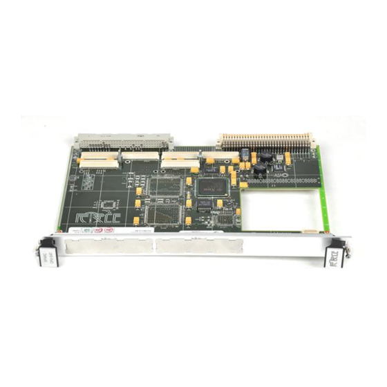
Figure 3 SPARC/CPU-54
39
Order Numbers
39
Table 3 Excerpt from the SPARC/CPU-54 Ordering Information for CPU Boards
39
Table 4 Excerpt from the SPARC/CPU-54 Ordering Information for Memory Modules
39
Table 5 Excerpt from the SPARC/CPU-54 Ordering Information for Accessories
40
2 Installation
42
Action Plan
44
Requirements
45
Environmental Requirements
45
Power Consumption
46
Table 7 Maximum Power Consumption
47
Table 8 Maximum Power Consumption with SPARC/MEM-54 Installed
47
Software Requirements
48
Hardware and Software Upgrades and Accessories
49
Memory Modules
49
Sparc/Iobp-54
50
Solaris Driver Package
50
Setting the SCSI Termination
51
SCSI 1 Termination
51
SCSI 2 Termination
51
Figure 5 SCSI Termination Concept of SPARC/CPU-54 and IOBP-54
52
Switch Settings
53
Figure 6 Location of Switches on Board's Top Side
53
Board Installation
57
Backplane Configuration
57
Installing the CPU Board
58
Removing the CPU Board
58
Table 9 Switch Settings
58
Powering up
59
Boot Devices OTP PROM and Flash EPROM
59
User Application
59
Installing Solaris
60
Solaris 8
61
Solaris Driver Package
62
Table 12 Devices and Their Appropriate Drivers
62
Table 13 Hardware Node Assignment
63
Table 14 Instance Number Assignment for SPARC/CPU-54
63
Table 15 Flash Segmentation and Write Protection
64
3 Controls, Indicators, and Connectors
66
Front Panel of the SPARC/CPU-54
68
Figure 8 SPARC/CPU-54 Front Panel
68
Leds
69
Table 16 Description of Front Panel Leds
69
Figure 9 Front Panel Leds
69
Keys
70
Reset
70
Abort
70
Mode
70
Connectors
71
Ethernet
71
Figure 10 Twisted-Pair Ethernet Connector Pinout
71
Serial I/O
72
Keyboard/Mouse
73
Figure 13 Keyboard/Mouse Connector Pinout SUN-Type Function
73
Figure 14 Keyboard/Mouse Connector Pinout PS/2-Type Function
73
Scsi
74
Figure 15 68-Pin Ultra-Wide SCSI Connector Pinout
74
On-Board Connectors of the SPARC/CPU-54
75
Table 17 On-Board Connectors
75
Table 18 P2 Backplane Connector Signals
75
Figure 16 P2 Vmebus Connector Pinout Rows Z-B
76
Figure 17 P2 Vmebus Connector Pinout Continued Rows C+D
77
4 Openboot Firmware
78
Introduction
80
Core
80
Figure 18 System Overview
81
CORE Workflow
82
CORE Commands
83
Openboot
83
Optional Boot Parameters
84
Boot Devices
84
Table 19 Boot Parameters
84
Table 20 Device Alias Definitions for SCSI#1
85
Table 21 Device Alias Definitions for SCSI#2
86
Post
83
Obdiag
87
Table 22 Other Device Alias Definitions
87
Figure 19 OBDIAG Main Menu
88
Table 23 OBDIAG Commands
89
Vxworks Support
90
NVRAM Boot Parameters
91
Table 24 Setting Configuration Parameters
91
Diagnostics
92
SCSI Bus
92
Table 25 Diagnostic Routines
92
All SCSI Buses
93
Clock
94
Group of Devices
94
Single Device
94
Network
95
Displaying System Information
96
Ethernet Address and Host ID
96
Figure 20 48-Bit (6-Byte) Ethernet Address
96
Figure 21 32-Bit (4-Byte) Host ID
96
ID Prom
97
Table 26 Commands to Display System Information
97
Resetting the System
98
Activating Openboot Help
99
5 Maps and Registers
102
Address Map
104
Table 27 PCI Addresses Considered by the PCI-To-Ebus2 Controller
104
Status and Control Register
105
Table 28 System Configuration Register Overview
105
User LED Control Registers
107
User LED 1 Control Register
107
Table 29 User LED 1 Control Register
107
User LED 2 Control Register
108
Table 30 User LED 2 Control Register
108
Control Register
109
Table 31 Control Register
109
Control and Status Register
110
Table 32 Control and Status Register
110
Watchdog Timer and Temperature Control Register
111
Watchdog Timer and Temperature Control Status Register
111
Table 33 Watchdog Timer and Temperature Control Status Register
111
Watchdog Timer Trigger Register
112
Table 34 Watchdog Timer Trigger Register
112
SYSFAIL and ACFAIL Interrupt Control Register
113
Table 35 SYSFAIL and ACFAIL Interrupt Control Register
113
Reset Status Register
114
Table 36 Reset Status Register
114
System Configuration Identification Register
115
Seven-Segment LED Display Control Register
115
Table 37 System Configuration Register
115
Table 38 Seven-Segment LED Display Control Register
115
Switch Status Register
117
Serial Protocol Status Register
117
Rotary Switch Status Register
117
Table 39 Serial Protocol Status Register
117
Table 40 Rotary Switch Status Register
117
Switch 4 and 5 Status Register
118
Table 41 Rotary Switch Settings
118
Table 42 Switch 4 and 5 Status Register
118
Switch 800 Status Register
119
Table 43 Switch 800 Status Register
119
Table 44 Timer Control Register
120
Timer Control Register
120
Timer Register
120
Table 45 Timer Initial Control Register L
121
Table 46 Timer Initial Control Register U
121
Table 47 Timer Counter Control Register L
121
Table 48 Timer Counter Control Register L
121
Timer Counter Status Register L
121
Timer Counter Status Register U
121
Timer Initial Control Register L
121
Timer Initial Control Register U
121
RS-422 Control and Status Register
122
Table 49 RS-422 Control and Status Register
122
Ethernet Control and Status Register
123
Table 50 Ethernet Control and Status Register
123
Troubleshooting
124
Battery Exchange
130
Index
134
Product Error Report
136
Advertisement
Advertisement
Related Products
Force Computers SPARC CPU-5CE
Force Computers SPARC CPU-3CE
Force Computers Centellis CT 16000 Series
Force Computers SPARC/CPU-5TE
Force Computers SYS68K/ DRAM-E3Ml
Force Computers Categories
Single board computers
Motherboard
Enclosure
Chassis
Control Unit
More Force Computers Manuals
Login
Sign In
OR
Sign in with Facebook
Sign in with Google
Upload manual
Upload from disk
Upload from URL