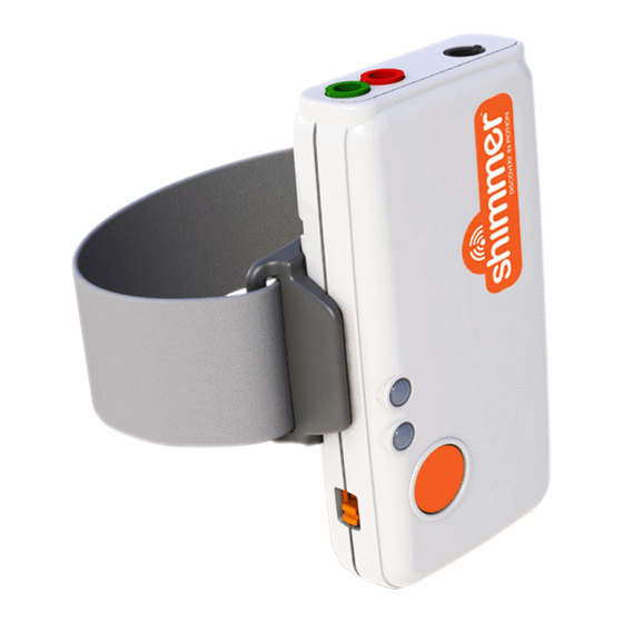
Shimmer 3 User Manual
Ecg respiration
Hide thumbs
Also See for 3:
- User manual (76 pages) ,
- Getting started (18 pages) ,
- User manual (29 pages)
Subscribe to Our Youtube Channel
Summary of Contents for Shimmer 3
- Page 1 Copyright © Shimmer Research 2013 Realtime Technologies Ltd IMU User Manual All rights reserved Rev 1.1 ECG Respiration User Guide Revision 1.1...
- Page 2 Neither the name of Shimmer Research, or Realtime Technologies Ltd. nor the names of its contributors may be used to endorse or promote products derived from this document without specific prior written permission.
-
Page 3: Table Of Contents
Copyright © Shimmer 2018 Realtime Technologies Ltd ECG Respiration User Guide All rights reserved Rev 1.1 Table of Contents Introduction ..........................3 General Information ......................... 4 2.1. Safety Information ......................4 2.2. Pre-Requisites ........................4 2.3. ECG Unit Specification Overview ..................4 Electrode Placement ......................... -
Page 4: Introduction
Copyright © Shimmer 2018 Realtime Technologies Ltd ECG Respiration User Guide All rights reserved Rev 1.1 1. Introduction The Shimmer3 ECG unit can be configured to measure respiration. This document provides recommendations regarding electrode placement, configuration settings for respiration detection, as well as an illustration of the signals that can be achieved from the device before and after post-processing. -
Page 5: General Information
In order to check if respiration detection is supported on your Shimmer3 ECG unit, please use Consensys and, with your Shimmer unit docked, refer to the "Expansion" board information shown on-screen. If the expansion board appears as "ECG/EMG/Respiration", respiration mode is supported. -
Page 6: Electrode Placement
In this guide, we recommend the top of the mid- axillary line on either side of the chest. Other locations can also be used [3]. Figure 3-1 provides a side view of the axillary lines. - Page 7 All rights reserved Rev 1.1 Figure 3-2 shows a recommended electrode placement layout on the body. The reference electrode, RL (green), input should be placed on the top of the right leg. The LA (black) electrode should be placed in the "V6" ECG electrode position (i.e., on the top of the mid-axillary line, on the left side of the body, at the sixth inter-costal space).
- Page 8 Realtime Technologies Ltd ECG Respiration User Guide All rights reserved Rev 1.1 Table 3-1 gives an overview of the input connectors and the recommended electrode positions for achieving the best respiration signal quality. Input Electrode Position Mid-Axillary line - right-hand side Mid-Axillary line - left-hand side ("V6")
-
Page 9: Configuration
Steps to enable respiration detection: 1. Set a minimum sample rate of 204.8Hz. 2. Enable "Respiration". 3. Set the gain to 3. 4. Write the configuration. For the default configuration the Respiration Detection Frequency is 32 kHz and Respiration Detection Phase is 112.5°. -
Page 10: Advanced Configuration
These parameters can be changed by modifying the values of the ExG Configuration Bytes directly, or by using the drop-down menus highlighted in Figure 4-3. The drop-down menu for the PGA gain can be found on the "ECG/EMG" configuration tile, see Figure 4-1 or Figure 4-2. For background information on the Respiration Detection signal, refer to [1]. - Page 11 All rights reserved Rev 1.1 ExG Configuration Bytes Figure 4-3 Advanced ECG/EMG menu Respiration Advanced chip configuration bytes: For respiration detection, the configuration bytes of the ADS1292R chips need to be configured as per Figure 4-4 below. This allows both chips to be synchronized at the same sampling clock and also...
-
Page 12: Example With Post-Processing
Shimmer and the resulting respiration waveform is presented as an output channel from the Shimmer while streaming/logging, see page 3 of [1] for a block diagram of this concept. Since the ADS1292r chip does not contain a low-pass filter in the signal path between the demodulated respiration signal and the AD-converter (as shown in page 3 of [1]), unwanted high-frequency content is still present in the signals. - Page 13 Blackman-Windowed Sinc-filter with 120 taps and a cut-off frequency of 2Hz. Figure 5-2 Low-pass filtered respiration signal Finally, Figure 5-3 also includes the ECG "LL-RA" signal; before and after filtering. The filter used is a low-pass Blackman-Windowed Sinc-filter with 120 taps and a cut-off frequency of 30Hz.
-
Page 14: References
[2] Texas Instruments, “Low-Power, 2-Channel, 24-Bit Analog Front-End for Biopotential Measurements,” 2012. [3] G. B. Drummond, a F. Nimmo, and R. a Elton, “Thoracic impedance used for measuring chest wall movement in postoperative patients.,” Br. J. Anaesth., vol. 77, no. 3, pp. 327–32, 1996. -
Page 15: Appendices
7. Appendices 7.1. ExG configuration bytes The relevant ADS1292R configuration bytes for respiration measurement are included in Table 7-1, Table 7-2 and Table 7-3, for convenience. Please refer to [2] for more detailed information. On/Off Mask (hex) Byte Value (hex) - Page 16 Copyright © Shimmer 2018 Realtime Technologies Ltd ECG Respiration User Guide All rights reserved Rev 1.1...


Need help?
Do you have a question about the 3 and is the answer not in the manual?
Questions and answers