
Related Manuals for Baker Hughes Masoneilan V-Max 36005 Series


Summary of Contents for Baker Hughes Masoneilan V-Max 36005 Series
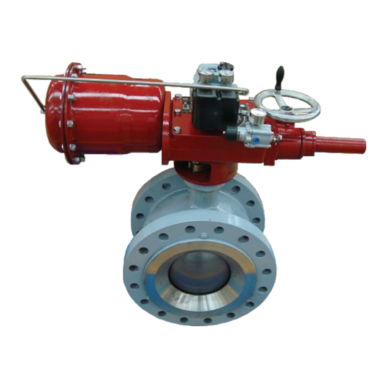
- Page 1 Masoneilan ™ 36005 Series V-Max ™ High Capacity Control Ball Valve Instruction Manual (Rev.E) Baker Hughes Data Classification: Public...
- Page 2 OPERATOR ARE STRICTLY LIMITED TO THOSE EXPRESSLY PROVIDED IN THE CONTRACT RELATING TO THE SUPPLY OF THE EQUIPMENT. NO ADDITIONAL REPRESENTATIONS OR WARRANTIES BY BAKER HUGHES REGARDING THE EQUIPMENT OR ITS USE ARE GIVEN OR IMPLIED BY THE ISSUE OF THESE INSTRUCTIONS.
-
Page 3: Table Of Contents
Figure 6 — Handwheel Bracket Detail, Sizes B & C ..............16 Figure 7 — Handwheel Lever Detail, Sizes B & C ..............16 Copyright 2020 Baker Hughes Company. All rights reserved. Masoneilan 36005 Series Control Ball Valves Instruction Manual | c... - Page 4 Table 2 — Bracket and Linkage Parts List ................21 Table 3 — Handwheel Parts List ....................22 Table 4 — Actuator Parts List ....................22 Table 5 — Line Bolting ......................23 d | Baker Hughes Copyright 2020 Baker Hughes Company. All rights reserved.
-
Page 5: Important : Safety Warning
Warranty DANGER CAUTION Items sold by Baker Hughes are warranted to be free from defects WARNING in materials and workmanship for a period of one year from the date of shipment provided said items are used according to Indicates a potentially hazardous situation which, if not avoided, Baker Hughes recommended usages. -
Page 6: Introduction
Masoneilan replacement parts. Parts are obtainable through your local Baker Hughes Masoneilan Representative or District Baker Hughes has highly skilled Service Engineers available for Office. When ordering parts always include MODEL and SERIAL start-up, maintenance and repair of our valves and component NUMBER of the unit being repaired. - Page 7 Actuator Position in Relation to Valve Body Numbering System: 1 to 8 Actuator Model 33, Size AC Actuator Model 33, Sizes B and C Copyright 2020 Baker Hughes Company. All rights reserved. Masoneilan 36005 Series Control Ball Valves Instruction Manual | 3...
-
Page 8: Installation
If necessary, scribe a witness line on the lever (32) in relation to the slot on the end of the shaft (5). Note: Standard lever has arrows stamped into it for alignment. For handwheel lever use slot for alignment. 4 | Baker Hughes Copyright 2020 Baker Hughes Company. All rights reserved. - Page 9 (25) and replace packing flange stud nuts (24). Replace handwheel assembly in bracket (62), pivot pins (72) DANGER and retaining clips (63). DANGER Copyright 2020 Baker Hughes Company. All rights reserved. Masoneilan 36005 Series Control Ball Valves Instruction Manual | 5...
-
Page 10: Changing Valve Action
For both air to open and air to close action, stroke valve fully the actuator is in the proper position. to ensure proper closure of ball plug and operation of valve. Tighten rod end bearing locknut (93). 6 | Baker Hughes Copyright 2020 Baker Hughes Company. All rights reserved. -
Page 11: Maintenance
Loosen cap screw (33) and indicator arm (35). Remove DANGER packing flange stud nuts (24) and bracket mounting stud nuts (26) and washers (18). Copyright 2020 Baker Hughes Company. All rights reserved. Masoneilan 36005 Series Control Ball Valves Instruction Manual | 7... -
Page 12: Bracket Subassembly Model 33, Sizes Ac
(32) and rod end bearing (94) line up. Install pivot pin of travel. There is a 1/2" adjustment available at the end of DANGER (39) and clips (40). 8 | Baker Hughes Copyright 2020 Baker Hughes Company. All rights reserved. -
Page 13: Body Subassembly
(2). Allow the graphite spray to dry fully – which will produce a dull gray finish on the coated parts. Copyright 2020 Baker Hughes Company. All rights reserved. Masoneilan 36005 Series Control Ball Valves Instruction Manual | 9... -
Page 14: Heavy Duty Metal Seal Ring
G. Apply pipe sealant to the safety pin, install into bonnet and tighten. Remove screws (9) and washers (10). Slide the retainer (3) out of the valve body. Remove seal assembly (refer to Para. 3.2.2.1 Seal Ring - Disassembly). 10 | Baker Hughes Copyright 2020 Baker Hughes Company. All rights reserved. -
Page 15: Actuator Subassembly
G. Replace side covers (46) and reconnect signal and supply lines. H. Place back in service and, if so equipped, rotate handwheel to desired position. Copyright 2020 Baker Hughes Company. All rights reserved. Masoneilan 36005 Series Control Ball Valves Instruction Manual | 11... -
Page 16: Handwheel Subassembly
Clean all mating/sealing surfaces which will come in contact with the diaphragm (85). 3.5.1.2 Reassembly (Figure 5) Install thrust washer (61) and 0-ring (57). Apply silicone lubricant sparingly to 0-ring. 12 | Baker Hughes Copyright 2020 Baker Hughes Company. All rights reserved. -
Page 17: Diaphragm Replacement
Relieve actuator pressure and disconnect air supply. Do not remove pivot pin (39). Verify that all three tension bolts (95) and nuts (96) are in place and secure. Copyright 2020 Baker Hughes Company. All rights reserved. Masoneilan 36005 Series Control Ball Valves Instruction Manual | 13... - Page 18 (86) to 50 in. lbs. in a criss-cross pattern until joint is evenly loaded to specified torque values. H. Reconnect air supply. Stroke actuator to confirm operation. 14 | Baker Hughes Copyright 2020 Baker Hughes Company. All rights reserved.
-
Page 19: Figure 2 - General Assembly
Copyright 2020 Baker Hughes Company. All rights reserved. Masoneilan 36005 Series Control Ball Valves Instruction Manual | 15... -
Page 20: Figure 3 - Actuator Sizes B & C Bracket & Linkage
16 | Baker Hughes Copyright 2020 Baker Hughes Company. All rights reserved. - Page 21 Copyright 2020 Baker Hughes Company. All rights reserved. Masoneilan 36005 Series Control Ball Valves Instruction Manual | 17...
- Page 22 18 | Baker Hughes Copyright 2020 Baker Hughes Company. All rights reserved.
- Page 23 Copyright 2020 Baker Hughes Company. All rights reserved. Masoneilan 36005 Series Control Ball Valves Instruction Manual | 19...
- Page 24 20 | Baker Hughes Copyright 2020 Baker Hughes Company. All rights reserved.
-
Page 25: Table 1 - Body Parts List
Nut, End Flange Thread Plug Stud, Packing Flange Stud, Bonnet Safety Pin Packing Adapter Shaft Ring Radial Seal Wave Spring Backup Ring Copyright 2020 Baker Hughes Company. All rights reserved. Masoneilan 36005 Series Control Ball Valves Instruction Manual | 21... -
Page 26: Table 3 - Handwheel Parts List
Bearing Race Thrust Washer Handwheel Bracket Retaining Clip Lever Arm Lever Arm Bearing Clevis Pin Guide Lever Arm PIn Spacer Cap Screw Lockwasher Pivot PIn Size AC Actuator Only 22 | Baker Hughes Copyright 2020 Baker Hughes Company. All rights reserved. -
Page 27: Table 5 - Line Bolting
4 1/2" 6" 6" 6" 4 3/4" 6 3/4" 8" 6" 5 1/4" 6 1/2" 10" 7" 5 1/2" 6" 12" 7 1/2" Copyright 2020 Baker Hughes Company. All rights reserved. Masoneilan 36005 Series Control Ball Valves Instruction Manual | 23... - Page 28 Baker Hughes reserves the right to make changes in specifications and features shown herein, or discontinue the product described at any time without notice or obligation.
Need help?
Do you have a question about the Masoneilan V-Max 36005 Series and is the answer not in the manual?
Questions and answers