
Related Manuals for Holman Dial Ezy


Summary of Contents for Holman Dial Ezy
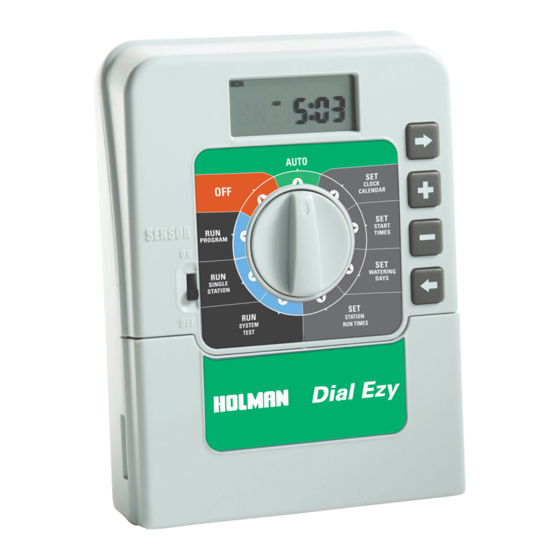
- Page 1 Dial Ezy IRRIGATION CONTROLLER 4 or 6 Station Model INSTRUCTION MANUAL SUITABLE FOR INDOOR USE ONLY OTHERWISE WARRANTY IS VOID N10372...
-
Page 2: Table Of Contents
Table Of Contents Features Glossary Programming Instructions Introduction Programming Example Other Functions General tips for programming Programming Set Current Time & Correct Day Set Calendar (Optional) Step 1. Set Start Times Step 2. Set Watering Days Individual Day Selection Odd / Even Day Selection Interval Day Selection Step 3. -
Page 3: Features
Features This unit is available in a 4 or 6 station configuration. Designed for residential applications, this controller has four separate start times and each can be programmed individually to suit your watering needs. These different areas may require individual watering programs and often use different types of sprinklers. -
Page 4: Glossary
Glossary Indoor Controller Model Selection Dial LCD Display Programming Used for Easy to read Buttons operations & display. Used for adjusting programming. the programmed information. Rain Sensor Switch Manually activate rain sensor by switching to ON/OFF position. Fuse Terminal Cover Remove to access terminals for Location solenoid (valve) wires and to annually... -
Page 5: Programming Instructions Introduction
Programming Instructions Introduction This controller has been designed with four separate starts (programming schedules), to allow different garden areas to have their own individual watering requirements. A program is basically a method of grouping stations (valves) with similar watering requirements to water on the same days. These stations will water in sequential order from the lowest number at the start time (or times) nominated and on the days selected. -
Page 6: Programming Example
Programming Instructions Programming Example A typical 6 station system is illustrated below. This guide will assist you when completing your watering planner. In this example the lawn areas are using pop-up sprinklers & require less frequent watering. The vegetables are watered using drippers, with a longer run time & the flower beds/pergola areas are watered with micro spray nozzles. -
Page 7: Other Functions
Programming Instructions Other Functions This controller can also manually run a selected start once, or an individual station can be set to run once from 1 minute up to 12 hours and 59 minutes. During winter the automatic start times can be suspended to prevent watering while it is raining. -
Page 8: Programming
Programming Set Current Time & Correct Day Turn the dial to Set Clock/Calendar position. The minutes will be flashing. Use to adjust. Press the button and the “hours” will flash. to adjust. Note: AM / PM must be set correctly. Press and the “day of the week”... -
Page 9: Step 1. Set Start Times
Programming Setting Start Each start time can be programmed individually to suit your watering requirements STEP 1. Set Start Times All valves will activate in sequential order for each start time. Turn the dial to Set Start Times. The display will show: “Start 1”... -
Page 10: Step 2. Set Watering Days
Programming STEP 2. Set Watering Days This unit has a 7 day calendar with individual day selection. Turn the dial to Set Watering Days. Individual Day Selection This is the selectable day option. The display will show: This refers to Mon being Day 1. To turn Monday off, press button. -
Page 11: Interval Day Selection
Programming If you require the ODD / EVEN day option, simply press the button until “EVEN” is shown. Press the button and “ODD” will be shown. Press the button and “ODD-31” . This feature may be required in areas where water restrictions are enforced. Note: Remember to set the 365 day calendar when setting the clock, or this feature will be out of sequence. - Page 12 Programming To adjust the Run time in minutes press , and use To set the run time in hours, press and “0” will appear and flash. To adjust use If not required, press , and advance to station 2 by pressing the button.
-
Page 13: Manual Operations System Test Facility
Manual Operations System Test Facility Turn the dial to Run System Test. There will be a one second pause The display will show: Use this feature to check that your valves & sprinklers are working correctly. The unit will run all stations in sequential order. The factory preset time of 2 minutes per station can be adjusted. -
Page 14: Run A Program
Manual Operations (cont.) Run A Start To manually run a complete start once for the run times as set in the automatic schedule, turn the dial to the Run a Start position. “Start 1” will be shown in the display. To run start 1, leave, or advance to start 2 by pressing Other Features Stop To stop an automatic or manual watering schedule, turn the dial to the... -
Page 15: Fitting A Rain Sensor (Optional)
Other Features Fitting a Rain Sensor (optional) A rain sensor can be wired directly into the terminal block. When the sensor is wet, all automatic and manual watering will not operate. To fit a rain sensor follow this procedure: 1. The sensor switch, accessed on the fascia, must be up in the “ON”... -
Page 16: Rain Off Mode
Other Features Rain Off Mode To stop the automatic watering cycles during winter, turn the dial to the Off position. The word “Off” will appear in the display. This means the automatic programs will not come on, but the programmed information is still retained in the memory. -
Page 17: Installation Instructions
Installation Instructions Mounting The Controller This controller unit is an INDOOR MODEL and MUST NOT be exposed to rain or water ingress, or direct sunlight. Install the controller near a 240V AC mains outlet, preferably located in a house, garage or other covered area. For ease of operation, eye level placement is recommended. -
Page 18: Field Wiring Connections
Installation Instructions Field Wiring Connections PREPARATION 1. Prepare wires for hook-up by cutting the wires to the correct length and stripping approximately 6mm (¼ inch) of insulation from the end to be connected to the controller. 2. Ensure terminal block screws are loosened sufficiently to permit easy access for wire ends. -
Page 19: Power Supply Connections
Installation Instructions Power Supply Connections The controller itself can run off a 240V AC to 24V AC external transformer. It is recommended that the transformer is not connected to a 240V AC supply which is also servicing or supplying motors. (i.e. -
Page 20: Pump Hook-Up Connections
Installation Instructions Pump Hook-Up Connections DO NOT attempt to drive a pump starter directly from the controller. Pump start is provided by connecting one side of the coil of a suitable relay to the Master Valve/Pump Start output of the controller and the other side to the controller common. -
Page 21: Electrical Characteristics
Electrical Characteristics Power Supply MAINS SUPPLY This unit can run off a 50Hz external transformer, (plug pack), with an output of 24VAC 50Hz @ 1.0 Amp. Plug Pack Model The correct wiring installation for the 24VAC plug pack is shown on page 17. -
Page 22: Servicing The Controller
Servicing The Controller The controller should always be serviced by an authorised agent. Follow these steps: 1. Turn the mains power off to the controller. 2. Disconnect 24 Volt power leads from the plug pack at the controller 24VAC terminals. 3. -
Page 23: Fault Finding Guide
Fault Finding Guide Symptom Possible Cause Suggestion Faulty transformer. Check fuse. Check field wiring. No display. Fuse blown. Check transformer. Faulty solenoid coil. Swap faulty station wire on controller Single Station terminal block with known working not working. station wire. If the faulty valve still does not work on the known working connection then the solenoid coil is faulty. -
Page 24: Spare Watering Planners
Spare Watering Planner WATERING RUN TIME START TIME SCHEDULE (minutes) Start Time 1: Start Time 2: Start Time 3: Start Time 4:... - Page 25 Spare Watering Planner WATERING RUN TIME START TIME SCHEDULE (minutes) Start Time 1: Start Time 2: Start Time 3: Start Time 4:...
- Page 26 A copy of your original invoice. A description of any fault. It is the purchaser’s responsibility to return the Controller to the manufacturer or their agent by pre-paid freight. HOLMAN INDUSTRIES 47 Walters Drive Osborne Park Western Australia 6017 Tel: +61 8 9204 1011 Fax: +61 8 9204 1013...
Need help?
Do you have a question about the Dial Ezy and is the answer not in the manual?
Questions and answers