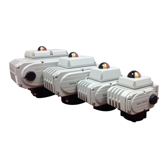
VSI 1000-X Series Operation And Maintenance Manual
Open/close service electric actuators
Hide thumbs
Also See for 1000-X Series:
- Installation, operation & manintenance manual (16 pages) ,
- Quick setup manual (2 pages)
Table of Contents
Advertisement
Advertisement
Table of Contents

Summary of Contents for VSI 1000-X Series
- Page 1 SERIES 1000-X OPEN/CLOSE SERVICE ELECTRIC ACTUATORS OPERATION AND MAINTENANCE MANUAL COMMERCIAL AND INDUSTRIAL VALVES AND AUTOMATION Publication S1000X-110 VER0815-2 For information on this product and other VSI products please visit our web page - www.valvesolutions.com...
-
Page 2: Table Of Contents
VSI Series 1000-X Electric Actuator Operation and Maintenance Manual CONTENTS Safety Instructions and Warnings Power Supply Requirements Component Names Application Requirements Overall Dimensions and Specifications Mounting on a Valve 1005-X Adjustment of Actuator 1010-X Operation Test 1020-X Thru 1060-X Maintenance and Service... -
Page 3: Component Names
VSI Series 1000-X Electric Actuator Operation and Maintenance Manual COMPONENT NAMES Side Gear Cover Worm Shaft Top Wiring Cover Override Socket Handwheel* Reducing Gear Group Front Wiring Cover Capacitor Push Button* Open Cam Lock Screw Conduit Plugs Close Cam Lock Screw... -
Page 4: Overall Dimensions And Specifications
VSI Series 1000-X Electric Actuator Operation and Maintenance Manual OVERALL DIMENSIONS AND SPECIFICATIONS FOR 1005-X AND 1005-XL 113[114] 160[162] 63[66] 49[48] 83[82] 77[80] Ø70 Ø70 Ø50 Fig. A Direct Mount Parameters Square Shaft 14 x 14 4-M8 Mounting Flanges Evenly Distributed Stem Height Height ≤... - Page 5 VSI Series 1000-X Electric Actuator Operation and Maintenance Manual OVERALL DIMENSIONS AND SPECIFICATIONS FOR 1010-X 95.5 100.5 Ø90 Ø70 Ø50 Fig. A 4-M8 Evenly Distributed Direct Mount Parameters 17 x 17 Square Shaft Mounting Flanges 4-M6 Stem Height Height ≤ 32mm...
- Page 6 VSI Series 1000-X Electric Actuator Operation and Maintenance Manual OVERALL DIMENSIONS AND SPECIFICATIONS FOR 1020-X THRU 1060-X Ø125 Ø102 Fig. A Ø70 4-M10 Evenly Distributed Direct Mount Parameters 27 x 27 Square Shaft Mounting Flanges Stem Height Height ≤ 45mm...
- Page 7 VSI Series 1000-X Electric Actuator Operation and Maintenance Manual OVERALL DIMENSIONS AND SPECIFICATIONS FOR 1100-X THRU 1250-X Ø135 Ø140 Fig. A 4-M16 Ø102 Evenly Distributed Direct Mount Parameters 36 x 36 Square Shaft Mounting Flanges Stem Height Height ≤ 54mm...
-
Page 8: 1010-X
VSI Series 1000-X Electric Actuator Operation and Maintenance Manual ELECTRICAL WIRING CONNECTION Contact Ratings FIELD WIRING Models AC Voltage DC Voltage ACTUATOR Y&G 1005-X and 1005-XL 3A/250VAC GREY FULL CLOSE SIGNAL 1010-X thru 1250-X 15A/250VAC 0.6A/125VDC BROWN FULL OPEN SIGNAL... -
Page 9: Application Requirements
VSI Series 1000-X Electric Actuator Operation and Maintenance Manual APPLICATION REQUIREMENTS Installation Conditions Conduit and Cable Installation (Cont.) • If actuator must be installed below conduit, a drip Series 1000-X units may be installed in indoor or • loop or drain should be provided to allow any water outdoor conditions up to IP67 or NEMA 4X to exit the piping. -
Page 10: Mounting On A Valve
VSI Series 1000-X Electric Actuator Operation and Maintenance Manual MOUNTING ON A VALVE Installation of Actuator to Valve 5° alignment, rotate actuator handwheel to move actuator into alignment. 1. NOTE: Direct mounting the actuator removes the 9. Drive the actuator using the manual crank or... -
Page 11: Adjustment Of Actuator
VSI Series 1000-X Electric Actuator Operation and Maintenance Manual ADJUSTMENT OF ACTUATOR Switch Adjustment 1. Using the manual handwheel or hand crank, drive the 4. If the contacts indicate continuity (switch activated): valve to the fully closed position. Visually inspect the valve a. -
Page 12: Operation Test
The dome indicator lens is broken Contact VSI Housing screws are not tightened and sealed Tighten housing screws Condensation heater not working or not Check heater connections or Contact VSI connected Valve Solutions Inc, LLC tel: (770) 740 0800 fax: (770) 740 8777...


Need help?
Do you have a question about the 1000-X Series and is the answer not in the manual?
Questions and answers