
Related Manuals for VSI VSN-104Z


Summary of Contents for VSI VSN-104Z
- Page 1 VSN-104Z INSTRUCTION MANUAL Head : VSH-10Z Controller : VSC-104Z Copyright 2014 VSI Co., Ltd. All rights reserved Contents of this publication may not be reproduced in any form without the written permission of VSI Co., Ltd. Page 1 / 23...
-
Page 2: Table Of Contents
Table of Contents 1. Part Names and Functions ..............3 2. Installation and Operation ..............6 3. Safety Instructions ................18 4. Decay Time ..................19 5. Product Specifications ............... 20 6. Components Included ............... 21 7. External Dimensions ................. 22 Page 2 / 23... - Page 3 Indications on Product ■ The following indications in the product can be seen ● Head Domestic version International version Page 3 / 23...
-
Page 4: Part Names And Functions
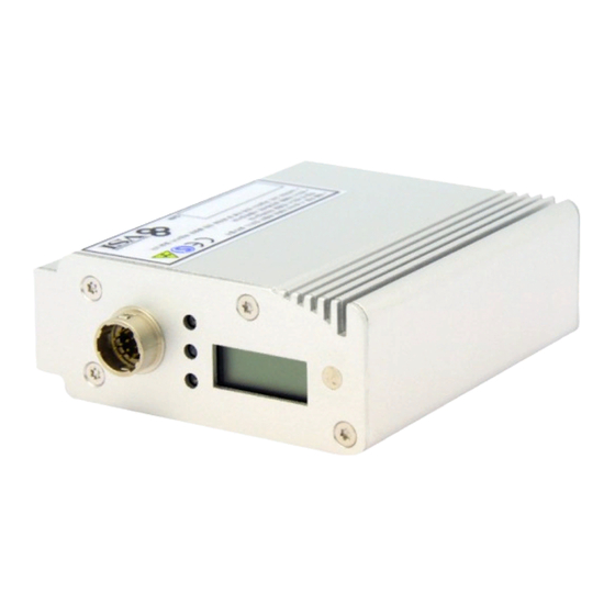
1. Part Names and Functions ■ Head (VSH-10Z) 1) Soft X-Ray window A window that irradiates soft X-ray that ionizes the air to eliminate static electricity. 2) Timer LCD The usage time (hour) of the head is displayed. 3) Run Indicator (Green Light) It turns on when the soft X-ray is being irradiated and a static elimination is occurring. - Page 5 ■ Controller (VSC-104Z) Front Panel Rear Panel ① Power(Green Light) : Green light will come on when the controller is powered. ② Interlock(Yellow Light) : It is a safety indicator lamp before soft X-ray is irradiated and it comes on when the interlock is connected. ③...
-
Page 6: Installation And Operation
2. Installation and Operation ■ Head Installation ① Fix the device using the holes on the fixture bracket and the screws supplied, at a desired location. ※ Please install the head in a shielded equipment. ② Install the head in a shielded location, the controller at a place with easy access, and connect the power and ground cables. - Page 7 ■ Controller Operation Method ① Before turning on the controller power switch, please connect the head and the controller using the connection cable. ② Turn on the power switch on the rear panel of the controller. (Red lamp will be lighted on the switch) ③...
- Page 8 ⑤ [Ionizer Irradiation ON] Push Run/Stop button on the front panel of the controller once. (For the Remote Ionizer Irradiation ON method, please refer to “2) Remote Signal Input Contents” on Page 12) During regular irradiation, the area around Run/Stop button will be lighted with white light, and LCD will display hourglass symbol.
- Page 9 ■ Controller Operation Status when Head FAIL Occurs Due to the abnormal operation of the head, the head red light will be lighted, and the Head Fail red light will be illuminated on the controller. The lamp for the failed head will be turned on.
- Page 10 ■ Controller Rear Panel Signal Input / Output Connections DSUB 15Pin Female Connector Pin Name Details Ground wire POWER Supplies +5V when the controller power switch is turned on. INTERLOCK ON Outputs +5V when pin 14 and 15 are closed. NORMAL Outputs +5V when soft X-ray is being irradiated.
- Page 11 1) Interlock Input Signal a) Interlock ON When the interlock contact connected to D-SUB 14 & 15 are closed, it is ready to irradiate soft X-ray. The Interlock on the front panel of the controller will be lighted. b) Interlock off When the interlock contact connected to D-SUB 14 &...
- Page 12 2) Remote Input Signal Remotely control the photo ionizer by inputting the control signal from the external (equipment side) to the D-Sub 15pin connector. - Control Mode 1 : D-SUB 9 & 10 Contact Open - Control Mode 2 : D-SUB 9 & 10 Contact Close a) Control Mode 1 ①...
- Page 13 b) Control Mode 2 ① Remote On Irradiates soft X-ray when D-Sub15pin 11 & 13 terminals are closed for more than 50ms. ② Remote OFF Does not irradiate when D-Sub15pin 12 & 13 terminals are closed for more than 50ms. Page 13 / 23...
- Page 14 Remote Operation Procedure ① Confirm that the head is installed in the shielded facility and the door with Interlock capability is closed. ② Turn on the controller's power switch. ※ The lamp on the front of the controller lights up for about one second. ③...
- Page 15 ■ Signal Input / Output Internal Circuit PhotoMos Input PhotoMos Output Page 15 / 23...
- Page 16 ■ Signal Input / Output Operation Examples 1) Example of using LED output drive and relay input ※ Parts may be damaged if external power Input (Each port +5V, 50mA max) is applied to the input side. Input side (must use switch contact) Unused ※...
- Page 17 2) Example of using TTL output drive and semiconductor contact input ※ Since the output side current uses a maximum 20mA output, it is necessary to drive the external LED, photo coupler, and TTL semiconductor and use the protection resistance after checking the driving current. 3) Example of Photocoupler Input / Output usage ※...
-
Page 18: Safety Instructions
3. Safety Instructions Head that emits soft X-ray during operation must be shielded for users’ safety. Since the shielding rate differs depending on the material, please refer to the following materials to design the shield. ● Point A: Shielding 10cm from the front of the X-ray window Shielding Material Thickness [mm] Stainless steel... -
Page 19: Decay Time
4. Decay Time Static electricity removal performance is represented by the time taken to drop the metal plate charged at ±1000V to ±100V by irradiating soft X-ray. unit : (sec) ※ Decay Time (when mounted): Top -> Down Irradiation, Based on straight line distance. -
Page 20: Product Specifications
5. Product Specifications HEAD Dimensions 63 x 31 x 89 mm X-Ray tube Tube voltage 11.0kV, Tube Electron emission Hot filament type Weight 261 g LED indicator Run / Over Time / Alarm Controller Dimensions 215x42x136 mm Fuse 250V, 3.15A, 1Ø , Glass type Weight 647 g Power consumption... -
Page 21: Components Included
6. Components Included Head/ 4ea Controller/ 1ea Head (VSH-10Z/Z-A) / 4ea 1:4 Type Controller (VSC-104Z) / 1ea Output Cable / H-OC-0010 Fixing Bolt / S-FB-0004 1/4”-20UNC X 15L /4ea, 10m / 4ea 1/4”-20UNC X 8L /4ea M4 x 0.7pich x 10L / 8ea PC-110-0018 Power Cable Signal Cable / 15Pin D-Sub AC 100V / 50,60Hz / 1.8m / 1ea... -
Page 22: External Dimensions
7. External Dimensions ■ Head Page 22 / 23... - Page 23 ■ Controller Page 23 / 23...
Need help?
Do you have a question about the VSN-104Z and is the answer not in the manual?
Questions and answers