Table of Contents
Advertisement
Quick Links
Advertisement
Table of Contents

Related Manuals for ANTEK DC6AT


Summary of Contents for ANTEK DC6AT
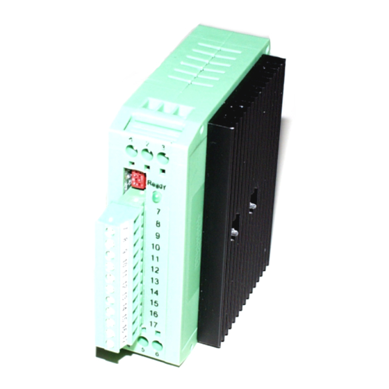
- Page 1 Operating Manual 1Q-Drive regulator of the series DC6AT...
- Page 2 Operating Manual 1Q- drive regulator DC6AT Document R0073dGB.doc Version 11/17...
-
Page 3: Table Of Contents
ONFIGURATION AND USEFUL INFORMATION ON PARAMETERS 5.2.1 R EAD ONLY PARAMETERS 5.2.2 D EVICE TYPE 5.2.3 O PERATING HOURS COUNTER 5.2.4 S TATUS 5.2.5 M EASUREMENTS 5.2.6 L OCKING TIME DURING CHANGE OF ROTATIONAL DIRECTION Operating manual DC6AT Page 3 of 28... - Page 4 6.1 R ESETTING FAULTS 6.2 P OSSIBLE CAUSES OF FAULTS 7. MAINTENANCE 8. MANUFACTURER’S DECLARATION 9. OPERATING SOFTWARE 9.1 UNIDESK 9.2 S ERIAL INTERFACE 10. INDEX -Errors and omissions excepted, subject to alterations- Page 4 of 28 Operating manual DC6AT...
-
Page 5: Preface And General
Quadrant 1. Quadrant 4: Speed negative, torque positive, the motor operates in regenerative mode. This corresponds to the situation in Quadrant 2, but in the opposite direction of rotation. Operating manual DC6AT Page 5 of 28... -
Page 6: Control Operation In Drive Controllers For 3- Phase Motors
3) and perform controlled braking in both directions (Quadrants 2 and 4). 1.2.2 Control operation in drive controllers for DC-motors ANTEK DC6AT series drive controllers hold the torque constant within very close tolerances without having to resort to a speed feed-back (tacho). The operating principle is based on a speed controller with underlying current controller. - Page 7 For good controlling behaviour of the drive controller, therefore, the correct setting of the pa- rameter R is very important. It contains not only the pure ohmic loss of the motor winding, but represents all losses that occur in the motor. Operating manual DC6AT Page 7 of 28...
-
Page 8: Extend Of Delivery
The following are shipped with the unit: ♦ 1 Drive Regulator DC6AT-xx-xx ♦ 1 Operating Manual ♦ connector X1 Upon receipt, examine the contents for completeness. The manufacturer, ANTEK - GmbH, assumes no liability for later shortage claims. 1.3.1 Brief description ♦ Overload-proof end stage ♦... -
Page 9: Proper Use
♦ The DC6AT series drive controllers are electronic controllers for control and adjustment of variable speed permanently excited DC motors ♦ The drive of the series DC6AT is intended for installation in switching cupboards or cabinets for drive systems. ♦ Drive systems incorporating the regulator DC6AT comply with EG-standards for EMI when installed per the directives for CE-typical drive systems. -
Page 10: Definitions
(Definition for qualified employees per IEC 364) Operator An operator is any natural person or legal entity who operates the inverter, or in whose name the frequency inverter is operated. Page 10 of 28 Operating manual DC6AT... -
Page 11: Safety
This also applies to the inter- action of the frequency inverter with the installation as a whole. Take additional measures to limit consequences of error functions which can prove to be dangerous for people: Operating manual DC6AT Page 11 of 28... -
Page 12: Operator Responsibilities
The drive regulator is a device for use in industrial, high-voltage systems. All covers must be in place during operation to prevent the possibility of electrical shock. Page 12 of 28 Operating manual DC6AT... -
Page 13: Technical Data
Chapter 3: TECHNICAL DATA 3. Technical data 3.1 Reference data DC6AT Type DC6AT DC6AT (UL) Nominal input voltage U in,nom 18...65 / 6…15 18...42 / 6…15 Input voltage range U Control Nominal input current I in,nom 0...98% U Output current U... -
Page 14: Key Values, Control Circuits
Cycle time current controller: 250 µs • 3.4 General Data / Operating Conditions Ambient temperature 50°C/(122°F) 0°C/(32°F) ... +40°C/(104°F) without power-loss 40°C/(104°F) ... +70°C/(158°F) with power-loss Output Power in % Temperature in °C Page 14 of 28 Operating manual DC6AT... - Page 15 Humidity class F without condensation (average relative humidity 85%) Degree of soiling: VDE 0110 Part 2 level 2 Interference emission: EN 50081-2, EN 50082-1 requirements Class B limits per EN 55011 (industrial range) Operating manual DC6AT Page 15 of 28...
- Page 16 Enclosure 8KV Connectors 4kV Voltage drops EN 61000-4-11 High frequency EN 50141 10V/m Voltage surge EN 61000-4-5 Class 1 Insulation: Over-voltage category II per VDE 0100 Protection class: IP 30 Mounting position: vertical Page 16 of 28 Operating manual DC6AT...
-
Page 17: Installation
♦ Tightening torque for field wiring terminals ♦ Use in a pollution degree 2 environment ♦ “Use Class 1 wire only” or equivalent Motor over temperature sensing according UL 508C is not provided by the drive or equivalent. Operating manual DC6AT Page 17 of 28... -
Page 18: Information On Emc
(GRD) or taut supports. cable taut support Generally all metallic conducting parts which can be connected to a protective conductor, such as cabinet frames, motor frames, foundation grounding (GRD), etc. is designated as a ground. Page 18 of 28 Operating manual DC6AT... -
Page 19: Connection
Pos. flank = reset fault message X1-14: Fixed speed _2 X1-15: Fixed speed _2 X1-16: Controller enable counter-clockwise rotation (CCR), HIGH = CCR active X1-17: Controller enable clockwise rotation (CR), HIGH = CR active Operating manual DC6AT Page 19 of 28... - Page 20 X1-12: Analogue set speed value Analogue signals must generally be shielded! 4.4.3.4 Digital message output Specification: max. switching voltage: 35 V≅ Ready message of drive controller max. switching current: 150 mA X1-7: Ready (potential-free) X1-8: Ready (potential-free) Page 20 of 28 Operating manual DC6AT...
-
Page 21: Service - Information
- IxR (factory parameter) - pulse Nominal speed 100 … 6000 min Feedback definition 10 … 2000 Feedback value filter 0 … 4096 Represented all losses in the motor, not only the ohmic winding resistor. Operating manual DC6AT Page 21 of 28... -
Page 22: Configuration And Useful Information On Parameters
The diagram below shows the time for the allowable over-current over the parameter “time- continuous over-current” for different over-currents, if the axis demonstrates no preload and maximum current is applied immediately. Page 22 of 28 Operating manual DC6AT... -
Page 23: Motor Constant
Offset 5.2.11 Threshold over temperature / overvoltage Safety limits of the device can only be changed by ANTEK. 5.2.12 Acceleration ramp Slope of the acceleration ramp 5.2.13 Response after fault Defines the behaviour after a fault (under/overvoltage, over temperature). A fault can be re- set either automatically after correction or externally through a reset flank (dependent on the setting of Parameter 12 –... -
Page 24: P/I Behaviour Speed Controller/Current Controller
5.2.17 Reset behaviour Defines whether the device can be reset by turning the controller enable off and on. It can only be changed by ANTEK. 5.2.18 End stage, motor output in case of fault In case of fault the end stage is blocked. Motor runs out without torque. -
Page 25: Finding And Eliminating Faults
♦ type of fault ♦ accompanying circumstances ♦ suspected cause of the fault ♦ unusual preceding events The device is equipped with a rapid monitoring system. Even short-term voltage interrup- tions can result in this fault. Operating manual DC6AT Page 25 of 28... -
Page 26: Maintenance
Inspect and clean the cooling fins regularly based on the degree of contamination. 8. Manufacturer’s declaration The manufacturer, ANTEK - GmbH, herewith declares that the drive regulator DC6AT must be used as a component of the control equipment for variable speed motors to be installed in a machine or to be used for the construction of a machine together with other components. -
Page 27: Operating Software
Chapter 9: OPERATING SOFTWARE 9. Operating software 9.1 UNIDESK In order to be able to parameterise and monitor the drive regulator DC6AT, ANTEK UniDesk monitor software is required. 9.2 Serial interface Communication between the monitoring program and the controller is handled by an ANTEK RS232 adapter with special connector and integrated level converter (5V <->... -
Page 28: Index
Frequency converter 27 switching voltage 20 Input resistance 20 terminal voltage 6, 7, 21 Input voltage 20 torque 5, 6, 24, 25 Input voltage range- 13 UniDesk 27 Installation 17 Voltage supply 19 Page 28 of 28 Operating manual DC6AT...
Need help?
Do you have a question about the DC6AT and is the answer not in the manual?
Questions and answers