Panasonic PressIT TY-WPS1 Operating Instructions Manual
Wireless presentation system
Hide thumbs
Also See for PressIT TY-WPS1:
- Operating instructions manual (28 pages) ,
- Operating instructions (functional manual) (65 pages) ,
- Operating instructions manual (28 pages)
Table of Contents
Advertisement
Quick Links
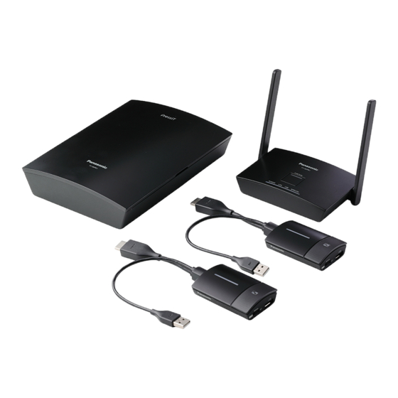
TY-WPS1
Model No.
WPS Basic Set
TY-WP2B1
WPS Transmitter Set
Thank you for purchasing the Panasonic product.
• Please read these instructions before operating this product and retain them for future reference.
• Be sure to read "Safety Precautions" (page 2 to 3) before use.
• These Operating Instructions are shared by TY-WPS1, TY-WP2B1, TY-WPB1, TY-WP2BC1 and TY-WPBC1.
English
DA0920TS0 -PB
Operating Instructions
Wireless Presentation System
Functional Manual
TY-WPB1
WPS Transmitter
TY-WP2BC1
WPS USB-C Transmitter Set
* WPS is an abbreviation of "Wireless Presentation System".
* PressIT is a nickname for "Wireless Presentation System".
For business use
TY-WPBC1
WPS USB-C Transmitter
DPQP1359ZA/X1
Advertisement
Table of Contents


Need help?
Do you have a question about the PressIT TY-WPS1 and is the answer not in the manual?
Questions and answers