
Related Manuals for LiCONiC StoreX STX40


Summary of Contents for LiCONiC StoreX STX40
- Page 1 (217) 352-9330 | Click HERE Find the Liconic Instruments STX40-HC at our website:...
- Page 2 Operating Manual StoreX Precision Incubator Series STX40, STX100, STX200, STX500, STX1000 IC, HC, HR, DC, DR, DF SA, BT, IT Artisan Technology Group - Quality Instrumentation ... Guaranteed | (888) 88-SOURCE | www.artisantg.com...
- Page 3 No license is granted by acquisition of the product for any patent or patent rights of LiCONiC. If the user does not follow the instructions given in this manual, LiCONiC does not take any responsibility for injuries or damages caused by the LiCONiC product.
-
Page 4: Table Of Contents
The StoreX Incubator Family..................8 StoreX Instruments......................8 LiCONiC StoreX Features ..................... 8 StoreX Configuration and Capacity Overview ............... 9 LiCONiC StoreX Climate Overview ................10 The StoreX 40 Handler....................11 The StoreX Carrousel Handler ..................12 Options ........................13 StoreX Climate Options ....................13 StoreX Configurations .................... - Page 5 Alarm System ......................66 7.10 Temperature Settings ....................66 7.11 Cleaning........................67 7.12 Disinfecting ......................... 67 7.13 Defrost ........................67 Remote Operation .....................68 RS-232 Serial Port Configuration ................68 Command Transmission Procedure ................68 Commands ........................73 Handling Status / Error Messages................78 Program Examples ......................
-
Page 6: About The Product And Its Manual
StoreX is intended to work as an element in an automated system. Unintended Use Due to its open architecture, the LiCONiC StoreX is NOT intended for clinical and diagnostic applications. These applications would be carried out by less qualified people, exposing them to dangerous liquids in the case of instrument malfunction. -
Page 7: Definitions
Definitions Operator: Any person who uses the equipment for its intended purpose. System Integrator: Authorized person company responsible installation, initial start up and overall safety of the system. Person or company who carries out service and maintenance tasks and is therefore contacted in the case of any problems with the system. -
Page 8: Safety - Basics
Only an authorized System Integrator shall carry out inspection, maintenance and repair tasks. 1.11.3 Spare Parts to be used Only original LiCONiC Spare Parts may be used. If other parts are used during the normal warranty period, the manufacturer's guarantee may be invalidated. 1.11.4 Modifications Modifications shall only be carried out by an authorized System Integrator. -
Page 9: The Storex Incubator Family
Storage and Automatic Plate Exchange Capability make StoreX the Rex (Latin: king) of storage in laboratory applications. LiCONiC StoreX Features All StoreX units have the same compact dimensions. StoreX has a user front door which allows comfortable and easy access for manual operation. The internal glass door allows visual inspection of the content and operation of the system without disturbing the internal climate. -
Page 10: Storex Configuration And Capacity Overview
StoreX Configuration and Capacity Overview The Family of StoreX is structured by their configuration, capacity in Microtiter plates and their climate StandAlone Configuration BenchTop Integrated StandAlone units are intended for operation on the ground while BenchTop models are for use on a table. The transfer position in SA units is 1000mm high while on BT units it is ~200mm. -
Page 11: Liconic Storex Climate Overview
LiCONiC StoreX Climate Overview Incubator ~33..50°C >95% RH Climate Humid Cooler 04..20°C 90..95% RH Dry Cooler 04..20°C <5%RH Humid Range 04..70°C 90..95%RH Dry Range 04..50°C <5%RH Deep Freezer -20°C The graphical chart below depicts an overview of the various climate ranges covered by each climate option. -
Page 12: The Storex 40 Handler
The StoreX 40 Handler Inside the StoreX climate chamber there is a handling system that allows random transport of plates. Plates can be moved internally as well as transferred to and from the environment. Access times are short and the internal climate is kept stable even for short time periods between accesses. -
Page 13: The Storex Carrousel Handler
The correct sequence of motions is monitored by initiators, by detecting the end- positions of motions. Initiators are foreseen for Shovel-In (11) and Shovel-Out Position (12) and Turn Save Range (13). For save operation, Gate-Open and Gate-Close Positions are detected. The Gate may only be closed when the Turn Save Initiator is active indicating the Handler is turned in. -
Page 14: Options
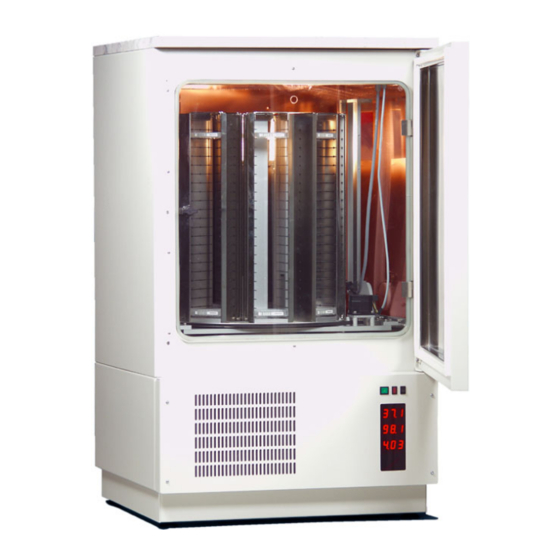
StoreX can be optimized for almost all known applications. The range of options is continuously growing. The list of options listed below is not a complete list. Please contact Liconic if you need functions not listed in this manual. - Page 15 The instrument’s controls and climate generator are located above the incubation chamber. The picture below shows a StoreX STX40 in BenchTop configuration. Note that only low capacity (up to ~200 plates) StoreX models are available in BenchTop. Larger capacity models are available as StandAlones only.
-
Page 16: Rh-Option
3.3.3 Copper Climate Chamber All StoreX are available with a full copper incubation chamber. This feature ensures a maximum protection against cross-contamination inside the incubation chamber. RH-Option The RH Option allows the display and control of humidity inside the incubation chamber. -
Page 17: Gassing Options
Specifications Measuring Range 0..100 % RH Accuracy@23°C ±1.5 % RH ±1.3 °K Temp. Resolution Bit / 0.02% Bit / 0.1°C Sensor PT100 Temperature Humidity Adjustment E2-PROM Gassing Options 3.5.1 Gassing Conditioner The Gassing conditioner is required for Gassing Options. Note that the Gassing Conditioner is required one time regardless of the number of Gassing Options used in a system. - Page 18 Principle of Operation The infra-red spectra of many gases are characterized by narrow, non- overlapping absorption bands. Thus, the measurement of absorption within a defined wavelength band can uniquely identify the presence and concentration of a particular gas. In NDIR gas sensors, an infrared optical 'sample' filter with a narrow band of transmission is selected to overlap with the absorption band of interest, the position of the filter determines which gas will be measured and the amount of absorption determines the gas concentration present.
- Page 19 3.5.3 N2 Nitrogen Option As StoreX incubators have to cope with frequent accesses they use a high quality N2 controller. The nitrogen measurement is based on an oxygen measurement. The N2 option therefore assumes that oxygen is displaced by nitrogen. The N2 Option of StoreX incubators consists of Gassing conditioner •...
-
Page 20: Uhs (Ultra High Speed) Option
O2 vol. for safety reasons. 3.5.5 Other Gassing Options There are other gassing options available. Please contact Liconic applications for further information. UHS (Ultra High Speed) Option Applications with very short access times. The access speed of the UHS handler is almost double compared to standard High Speed handlers. -
Page 21: Accessories
Deep Well Plates 50 mm The StoreX can handle almost every plate currently available on the market. For optimum performance LiCONiC offers a variety of stackers. Apart from the standard stacker sizes, customized sizes are available on request. Stacker Microtiter Plate... -
Page 22: Stx Transfer Stations
STX Transfer Stations 4.2.1 Standard Transfer Station A variety of transfer stations are available. The transfer station is accessed by the StoreX handler as well as any external robot. StoreX transfer stations allow most grippers access to the plate. All StoreX transfer stations are equipped with alignment pins that realign the plates in both horizontal directions. - Page 23 4.2.2 Turn Station The StoreX handler transports plates along their longer axis. Many systems require the plate to be presented at a rotation of 90 degrees. The Turn Station will rotate each plate before and after the access by the StoreX handler. Transfer Station Rotation Drive Rotation is controlled by the StoreX system.
-
Page 24: Slide Station
Slide Station When the distance of the transfer location to the StoreX is not sufficient, it may be extended by the Slide Station. The Slide Station has a linearly displaceable Transfer Plate. The travel path of the Transfer Plate is approximately 170 mm. Slide Drive The movements of the Shuttle Station are controlled by the StoreX system. -
Page 25: Shuttle Station
Shuttle Station The function of the shuttle-station is for the elimination of “inter transfer module”, space constants, and complications of adding robotic arms for distances of 170- 1000 mm. The source plates can be transferred from one work area to another with precision accuracy. - Page 26 4.5.2 NTP (Nano Titer Plate) Transfer Plate Transfer Plate for NTP (Nano Titer Plates) and other very high density plates. Attachment Bores This Transfer Plate is best suited for high alignment accuracy and for very light plates. This Transfer Plate can be equipped with Active Alignment for even higher alignment needs.
-
Page 27: Bar Code Reader
Bar Code Reader 4.6.1 General Information A Bar Code Reader can be installed on the Lift Assembly. It allows the reading of Bar Codes on plates stored in the stackers. Bar Codes have to be printed on the shorter side of the plates and have to face outwards to the StoreX Lift Assembly. Bar Code StoreX Lift Assembly... -
Page 28: Scheduler
Scheduler An independent Scheduler traces the location and specified duration of an item in the climate chamber, notifying you when the scheduled time is completed. The Scheduler is timed by the StoreX internal clock. Two operation modes can be selected: The Trace Mode monitors the length of time each plate has been in the climate chamber, notifying you at the time of the unloading of the plate. -
Page 29: Packing And Transport
Packing and Transport For transportation of the StoreX unit remove stackers from the climate chamber and secure the lift assembly in its turned-in position. Always use the original StoreX box for transportation. Do not lift the unit at the front door or at the Gate- Assembly. - Page 30 Foam Top Stackers Crate Lift the StoreX from the pallet base and carefully place it to the floor • Open the front door and remove the protective-wrapping from the lift • assembly Open the front door and remove the protective-wrapping from the lift •...
-
Page 31: Installation Of The Instrument
Installation of the Instrument Only a trained System Integrator should install the LiCONiC StoreX. Operate the instrument in a dry and clean environment only. Note that external climate situations may influence the performance of the instrument. CAUTION ! After installation of the StoreX with a System, do not move either of them. - Page 32 Allow ~ 10mm clearance between units Front Door Front Panel Allow min. 30mm clearance above ground Ventilation Slits Instruments with cooling options should not be operated immediately after transportation. Leave instrument turned off for at least 12 hours. The picture below shows another possibility for arranging StoreX units. This example depicts the combination of two StandAlone units and one BenchTop unit.
- Page 33 StoreX Bench Top StoreX Stand Alone A rear view of the instrument with some important measurements is given in the chapter “Transfer Station Adjustment“. CAUTION ! Never block the ventilation slits of an instrument Allow a minimum clearance of 30mm between the instrument and ground Instruments with cooling options must settle power-off for at least 12 hours Operate instrument in clean and dry environments only...
-
Page 34: Transfer Station Position
For adjustment of the transfer position use the utility software delivered with the StoreX unit. Note that the adjustment of the transfer position requires some basic mechanical skills. Improper action may damage the instrument. If needed call LiCONiC Customer Service for assistance. Gate Transfer Station... - Page 35 PC or laptop. A warning will appear. Read the warning carefully. If you understood the warning and understand this set-up procedure type ‘Y’ to continue. If you have questions contact Liconic or your integrator. StoreX STX_V078.doc CMa, 23.11.2009...
- Page 36 The program will now read the system constants. The constants are displayed during this operation. In case your StoreX has not been initialized, the program sends an initialization command.- Note that the initialization may take a few seconds. After initialization is finished a command screen appears. In the upper half of this screen some important system constants are displayed.
- Page 37 At this time that Gate should be opened and the StoreX handler should be turned out. The shovel is retracted. The pictures below give two views of this situation. Check visually whether the Transfer Station is adjusted so that the shovel will be able to travel freely into the Transfer Plate.
-
Page 38: Electrical Connections
The Gas Connector connects to an optional gas supply such as CO2, Oxygen or Nitrogen. Beware of the maximum gas pressure of 6 bar. CAUTION ! Switch the System off before connecting and disconnecting the LiCONiC StoreX Disconnect the RS-232 interface only with the power switched off... -
Page 39: Communication Connections
Prior to connecting the instrument to the power source choose the correct voltage setting and the appropriate fuse. The voltage selector is located at the rear of the instrument. Fuse Holder Voltage Selector Back panel The voltage setting is displayed in a small window in the fuse holder. CAUTION ! Beware of high voltage inside the instrument. - Page 40 Internal RS-232 Connector Cable Handshake-lines are short-circuited internally. StoreX STX_V078.doc CMa, 23.11.2009 Series Artisan Technology Group - Quality Instrumentation ... Guaranteed | (888) 88-SOURCE | www.artisantg.com...
-
Page 41: Gassing Installation
Gassing Installation 6.4.1 StoreX Gassing Options The StoreX series supports a wide selection of gassing options. Typical properties of some commonly used options are described next. There are other gassing options available. Note that each gassing option is linked to specific risks and hazards. - Page 42 WARNING ! In their liquid state inert gases are extremely cold fluids which can cause serious burns when in contact with the skin A cryogenic spill often gives a low lying cloud of vapor that creeps along the ground When a cryogenic liquid is released into the atmosphere, it evaporates and forms a dense cloud.
- Page 43 General Safety Instructions When working with inert gases prevent contact of liquid gas, cold vapors, or "snow" with exposed skin. Prevent entrapment of liquid in closed systems. Use only in well ventilated areas. Compressed gas cylinders contain gaseous and liquid gas at extremely high pressure and should be handled with care. Use a pressure-reducing regulator when connecting to lower pressure piping systems.
- Page 44 Limited access and exits • Increased likelihood of gas accumulation through leaks • Increased asphyxiation risk • Fire and explosion hazard • To be considered as confined spaces are the inside rooms of a building, laboratory rooms, machine pits, culverts, basement trenches for piping. When working in confined spaces, it is advisable that operators and other personnel are fully aware of the hazards of oxygen deficiency and adopt the following practices: A fully documented permit to work system...
- Page 45 Testing the oxygen content is desirable, although attention must be drawn to the fact that an analyzer alone is not absolute protection. Such equipment can always malfunction, unexpectedly be out of adjustment or detectors can be improperly positioned. Testing of oxygen content should therefore only be considered as an aid to the detection of a lack of oxygen.
- Page 46 6.4.4 System Installation On installations preferably choose pressurized cylinders rather then gas wall outlets. The use of cylinders will limit the amount of gas being spilled in case of fatal failure. Whenever a wall outlet installation is chosen, make sure that there is a remote shut off valve installed outside the room where the gas is used.
- Page 47 Two-stage pressure regulators are available from gas suppliers or laboratory accessories suppliers. The picture above shows an example of an installation. There is a wide variety of different models available. Your equipment may look different. The gas inlet of the StoreX is located on the back of the instrument. Attach the CO2 low pressure hose securely to the fitting.
- Page 48 Properties of Carbon Dioxide Carbon dioxide is colorless and odorless as gas or liquid. It is stored In containers under its own vapor pressure. If the pressure is suddenly relieved, the liquid rapidly cools as it evaporates and sublimes, forming dry ice at -78.5°C (- 109.3°F) Boiling Point @ 1 atm -78.5°C, -109.3°F...
- Page 49 6.4.6 Specific Advice for O2 Oxygen Properties of Oxygen Oxygen is the only gas, which supports life. The normal concentration in the air that we breathe is approximately 21%. The danger occurs when the oxygen levels in the air and the hazards of asphyxia become very great. Boiling Point @ 1 atm -183.0°C (-297.3°F) Freezing Point @ 1 atm...
- Page 50 To fight fires, shut off sources of oxygen and use conventional firefighting methods. Prevent liquid oxygen from coming into contact with grease, oil, asphalt or combustibles. Ventilate area to evaporate and disperse oxygen. Flush area with large quantities of water. DO NOT ENTER areas of high oxygen concentration, which can saturate clothing and increase its flammability.
- Page 51 On vaporization Nitrogen expands by a factor of 700; one liter of liquid nitrogen becomes 24.6 cubic feet of nitrogen gas. This can cause the explosion of a sealed container, or it can displace oxygen in the room and cause suffocation without warning.
- Page 52 An exhaust channels the surplus amount of gas to a defined point. The exhaust is usually connected to the slightly under-pressurized exhaust system of the building. The flow regulator is combined with a visual flow indicator and a scale calibrated in l/min. Open Loop System The Open Loop System uses a more ntelligent system that limits gas flow to the actual required amount.
- Page 53 Closed Loop System The Closed Loop System is the most advanced system that gives a very high level of accuracy and maximum flexibility. The gas consumption is limited to the actual required amount. This solution is suitable for high-accuracy applications where the incubation chamber has to be filled with specific gas concentrations that may even vary with time.
- Page 54 6.4.9 Integrated StoreX Gassing Safety Features There are a number of safety mechanisms implemented in the StoreX application that protect the user from unwanted exposure to gases.. Even in the case of failure or operation errors these mechanisms can ensure safe shut-off of the gas inlet.
- Page 55 The option of remote access to the gas concentration allows a simple tracing of the gas concentration over long periods of time. The safety features are summarized in a table given below. Feature Comment Pressure Limiter Limits internal pressure to some extent Gas Flow Limiter Limits maximum flow avoiding full gas flow Exhaust...
-
Page 56: About Other Hazardous Substances
About other Hazardous Substances 6.5.1 DMSO (Dimethyl Sulfoxide) Properties of DMSO (Dimethyl Sulfoxide) DMSO (Dimethyl Sulfoxide) is often used in cooled dry storages like the StoreX DC. DMSO is used in the synthesis of important pharmaceuticals such as Ranitidine, Clarithromycin and Ioverso. Important herbicides made with DMSO are: acifluorfen, oxyfluorfen, lactofen and haloxyfop. - Page 57 Store tightly closed in a cool and dry place. Keep away from heat and open flames. WARNING ! DMSO is quickly absorbed through the skin and is capable of transporting other dissolved chemicals or dissolved toxins into the body DMSO has unusual fire and explosions hazards StoreX STX_V078.doc CMa, 23.11.2009...
-
Page 58: Manual Operation
Manual Operation Routine Safety Checks Carefully read all Safety Instructions before operating the instrument. Be sure that you fully understand their content. Although the StoreX is intended to be operated as a remote controlled system there still are some manual interactions required for operation. -
Page 59: Front Door
Front Door The Front Door opens on the left side of the instrument and should be kept closed at all times. A Magnetic Seal keeps the Front Door closed. When access is necessary it should be for as short as possible periods. In order to avoid condensation and to allow an even temperature distribution inside the instrument, the Front Door is heated. -
Page 60: Glass Door
Glass Door Behind the Front Door is the Glass Door which allows inspection of the stored samples and observation of the functioning of the Handler while keeping the climate stable. The Glass Door may be opened on its left side but should be kept closed at all times. -
Page 61: Stackers
Stackers Stackers allow for simple and comfortable loading and unloading of storage samples and can be prepared outside the climate chamber. Once prepared the samples can be quickly transferred into the climate chamber of the StoreX unit. There is a wide variety of stacker types available. Make sure that you work with the proper stacker size that matches the type of plates you are using. - Page 62 The stacker plate must be kept clean as particles may cause it to tilt. Do not place stackers on the floor as they may pick-up dust etc. Always store stackers inside the climate chamber or on clean surfaces. Use stacker handle for transport. When lifting the stacker by its handle it will tilt backward slightly in order to prevent plates from shifting to the front.
- Page 63 Stacker Handle Stacker Stacker Back Stacker Plate The stackers are secured by alignment rails to the stacker plate. The stackers may be tilted slightly backwards (towards the front opening) for removal. In order to load a stacker align the back of the stacker base plate to the centering pins located on the stacker plate.
-
Page 64: Bar Code Reader
Bar Code Reader An optional Barcode Reader for microplate identification is mounted above the lift. Stacker shelf positions can be altered to hold 11 Half-heights or 7 Deep Well plates. However, this must be carried out by a trained System Integrator. The Barcodes must be placed on the shorter side of the plates and must face towards the open side of the stacker. -
Page 65: Humidity Reservoir
On instruments with internal carrousels a positioning key located in the front panel of the incubator is pressed for manual access. In order to accept a manual positioning, the key-switch next to the positioning switch has to be in the right position. -
Page 66: Power-On System
Power-On System The Instruments power is activated by the incubator’s main switch. The instrument is turned on by pressing the power switch located at the front of the instrument. After power-on the climate portion of the instrument is activated automatically. An alarm will sound. If the green light of the Power Switch does not turn on, check the Main Switch at the back of the instrument. -
Page 67: Alarm System
Alarm System The StoreX has a combined acoustic / visual alarm system. An alarm occurs when one or more abnormal statuses occur or when interaction is required. When the system is operating properly there is no alarm. The various alarms are distinguished by the alarm signal duration and the pause between the signals. -
Page 68: Cleaning
7.11 Cleaning WARNING ! Do not touch handling or interior with bare hands Some components of the handling may cause injuries Beware of open gears and sharp edges Do not perform cleaning operations if you did not receive adequate training Do not perform cleaning unless you are familiar with the content of the incubator 7.12... -
Page 69: Remote Operation
Remote Operation RS-232 Serial Port Configuration ASCII data format Full duplex PC: Delimiter CR (Chr 13h) PLC: Delimiter CR,LF (Chr 13h,10h) 9600 Baud 8 Data bits 1 Stop bit Parity even The example program shows how the comport is initialized under MS-DOS. For details refer to the MS-DOS manuals. - Page 70 8.2.2 Command Syntax For communication only a few commands are required. A command is an ASCII- string which is sent to the controller. Response is an ASCII string sent by the controller. Note that each command is prompted by a Response string. A command consists of command segments.
- Page 71 FUNCTION STX_ReadBackStr(pN:INTEGER; s:STRING):STRING; CONST tries=2; VAR i,n,m,err:INTEGER; w:WORD; s0,s1:STRING; c,kp:CHAR; BEGIN IF NOT(kbdEsc) THEN BEGIN EmptyAux(pN); i:=-1; s0:=s; m:=Pos('-',s0); IF m>0 THEN BEGIN Delete(s0,m,1); s1:=Copy(s0,m,Length(s0)); Val(s1,n,err); Delete(s0,m,Length(s0)); w:=-n; Str(w,s1); s0:=s0+s1 END; REPEAT Inc(i); EmptyAux(pN); auxStrOut(pN,s0+cr); IF i>3 THEN DelayMs(100); auxStrIn(pN,s1,5,lf); Delete(s1,PRED(Length(s1)),2) UNTIL (s1[1]<>'E') OR (i>tries) OR KbdEsc;...
- Page 72 These examples show how simple communication becomes when using the “STX_ReadBack” procedure. The following example explains how often used sequences are programmed. The ‘Set-‘procedure sets an internal relay (or flag). The value of the flag becomes ‘1’. The ‘Reset-‘procedure resets an internal relay (or flag) .
- Page 73 8.2.4 Controller Error Messages The following Error Codes are sent by the PLC. These error codes indicate system-errors and are not the same as the Instruments own error-messages (refer to “Handling Error Messages”) Error Comment Response Relay Error Undefined timer, counter, data memory, check if E0 cr lf requested unit is valid Command Error...
-
Page 74: Commands
A sample program will explain the polling sequence in detail. Note that monitoring a flag change either from ‘0’ to ‘1’ or from ‘1’ to ‘0’ may also be advisable. PROCEDURE STX_WaitReady(portNbr:INTEGER); BEGIN DelayMs(300); WHILE (STX_Read(portNbr,1915)='0') AND NOT(KeyPressed) DO DelayMs(200) END;... - Page 75 Stop Shaker RS sp 1913 cr OK cr lf Read Shovel Plate Sensor RD sp 1812 cr x cr lf Read Transfer Station Plate Sensor RD sp 1813 cr x cr lf Read 2 Transfer Station Sensor RD sp 1807 cr x cr lf Read Swap Station position RD sp 1912 cr...
- Page 76 8.3.2 Examples of Usage of Basic Commands The following example strings show the usage of the basic commands. To initialize the system after a cold-start or a reset you may send: Command Response Comment ST sp 1801 cr OK cr lf Initialize Command Prior to sending an initialization command you may request the system status by reading the Ready Flag:...
- Page 77 In order to transport one plate from level 15 of stacker 2 to level 17 of the same stacker 2 the following sequence has to be sent: Command Response Comment WR sp DM0 sp 2 cr OK cr lf Position rotation at slot 1 WR sp DM5 sp 17 cr OK cr lf Pick plate from level 17 of stacker 2...
- Page 78 Read Handler Left Stacker position (default RD DM80 ddddd cr lf ~70) Read Handler Right Stacker position (default RD DM81 ddddd cr lf ~940) Read Handler Transfer Station position RD DM82 ddddd cr lf (default ~3500) Set Handler z-Offset WR DM20 cr lf Set Handler dz Pick- &...
-
Page 79: Handling Status / Error Messages
8.3.5 Short Access Commands The following commands allow extremely short and simple command sequences. When using short commands the plates are numbered from 1 to the maximum plate capacity. The maximum plate capacity is the value in DM25 (number of levels) multiplied with the value in DM29 (number of stackers). - Page 80 does not move User Access Error Unauthorized user access in combination 00010 cr lf with manual rotation of carrousel Stacker Slot Error Stacker slot cannot be reached 00011 cr lf Remote Access Level Error Undefined stacker level has been 00012 cr lf requested Plate Transfer Detection...
- Page 81 Error Description Code Export Plate Lift Stacker Carrousel could not reach desired radial 00200 cr lf Travel Error position during Export Plate procedure or Lift could not reach desired stacker level during Exoprt Plate procedure. Export Plate Shovel Stacker Shovel could not reach front position on 00201 cr lf Front Error...
-
Page 82: Program Examples
The following example will show how the Ready Polling can be combined with the continuous system status request. The program below will display details of the handling actions of the StoreX handler. In combination with data base detailed status reports can be output real-time to the operator all time. PROCEDURE STX_WaitReadyTrace(portNbr:INTEGER);... - Page 83 StoreX STX_V078.doc CMa, 23.11.2009 Series Artisan Technology Group - Quality Instrumentation ... Guaranteed | (888) 88-SOURCE | www.artisantg.com...
- Page 84 A universally usable procedure which can be used for most StoreX commands is given below. Use this procedure after initializing the instrument only. PROCEDURE STX_DoPlate(pN,slot,level:INTEGER; command:STRING); BEGIN IF NOT(KeyPressed) THEN BEGIN STX_WaitReady(pN); STX_WriteDataMemory(pN,0,slot); STX_WriteDataMemory(pN,5,level); STX_Set(pN,command); STX_WaitReadyTrace(portNbr) END; END; StoreX STX_V078.doc CMa, 23.11.2009 Series Artisan Technology Group - Quality Instrumentation ...
-
Page 85: Utility Software
Utility Software LiCONiC R&D 01-06-96 C.G.Malin 09:04:01 HBI-UserSoft V 0.04, 25.05.96 ______________________________________________________________ Heraeus AG HBI 2001-3 UserName S-Nbr Direct Commands Monitor Flags Macros Teach Positioning Times Random Positioning Random Access Cycles Random Fast Access Quit ______________________________________________________________ Enter [0..7] 9.1.1 Direct Commands Direct entering of commands (ASCII-Characters) and sending to the Handling Controller. - Page 86 9.1.2 Monitor Flags 0000 Rot.EN 0500 0001 GateEN 0501 GtClse 0002 GateEN 0502 GtOpen 0003 Rot.Dir 0503 0004 GtTmOut 0504 F.Door 0005 AccsLED 0505 SW 2E0 0006 SW 2E1 0007 SW 2E2 0008 SW 2E3 0009 Acs. 1100 Key Valid InPos Ready 1915 RotPos.
-
Page 87: Macros
9.1.3 Macros Sending of complete, preprogrammed command sequences. Function Command Rot. Position WR DM0 x 1..9 Enable Rotation WR DM0 0 Gate Open ST 1901 Gate Close ST 1902 End Access ST 1903 Shaker ON ST 1907 Shaker OFF RS 1907 CarAct ON ST 1801 CarAct OFF... -
Page 88: Random Positioning
9.1.5 Random Positioning Program for positioning the carrousel randomly without gate movements. After entering the access intervals the program continuously simulates accesses at random positions until the “q-Key“ is pressed. As a result a table containing statistical data is presented. If an error of positioning time larger then 0.4 seconds compared with the calibrated positioning time is observed a positioning error is assumed and monitored. -
Page 89: Troubleshooting
Troubleshooting The following list shows the possible errors of a StoreX handler which can be fixed by the customer. If the steps below aren’t successful, please contact an authorized service personnel. CAUTION ! Never touch electrical connections as long the Handler is connected to the external net or one or more covers are removed. -
Page 90: Maintenance
Maintenance 11.1 Maintenance Guidelines Handler 4 can only be used in a clean and dust free environment (laboratory use). Dust can damage the open rotating parts. If the instrument is stored in a dusty, unclean atmosphere for a long period of time, the dust must be removed and the instrument must be cleaned very carefully before the instrument is installed. -
Page 91: Removal Of Storex Handling
Great care must be taken that all moving parts and cables of the Lift Assembly move freely without obstacle. Note that the above procedure requires mechanical skills. Improper operation may harm and/or damage the instrument. Please call LiCONiC Customer Service for additional information or customer training. CAUTION ! -
Page 92: Lubrication Of Handling Components
11.3 Lubrication of Handling Components For lubrication of the radial-lead there is a lubrication-hole on the front side of the Laufwagen. Put lubrication in the lubrication-hole until it floods the sealing on the side. For the Lift assembly lubricate at A, B as shown below. Make sure that the lubricant covers the entire length of the linear-guidance. -
Page 93: Bar Code Scanner
11.5 Bar Code Scanner WARNING ! Laser Class 2. Clean the Laser Beam Output Window only when the laser beam is deactivated. The Laser Beam Output Window must be perfectly clean at all times. Even slight soiling will cause reading errors. Daily Maintenance: Clean the Laser Beam Output Window thoroughly. -
Page 94: Technical Data
Technical Data 12.1 Mechanics • Slots (Standard config.) 2 MTP-Positions, max. load 5 kg • Levels 22, usable height / level 17mm • Lift drive Stepper Motor, bipolar, micro-stepping mode • Shovel drive DC-Motor • Gate Linear movement, heated • Noise <52dBA / 1m •... -
Page 95: Weights
StoreX 200 SA StoreX 40 StoreX 200 Stand Alone Bench Top Stand Alone Bench Top Width (W) 486 mm 486 mm 744mm 744 mm Depth (D) 514 mm 412 mm 716 mm 716 mm Height (H) 1223 mm 1180 mm 1223 mm 1180 mm Transfer Height (T) 1000 mm... -
Page 96: Appendix
Appendix 13.1 Decontamination instructions Prior to repairing or servicing the instrument or parts, shipping it to the distributor or manufacturer, the instrument or affected parts must be thoroughly decontaminated and a copy of this form should be filled out and enclosed with the instrument/parts.. ∗...
Need help?
Do you have a question about the StoreX STX40 and is the answer not in the manual?
Questions and answers