Table of Contents
Advertisement
Quick Links
iG8
GNSS RTK Receiver
with Internal Satel 1-Watt Radio
User Manual
This manual is for use with iG8 RTK GNSS receivers produced by iGage Mapping
Corporation.
Receivers purchased from other sources that appear to be similar will not
match devices provisioned by iGage.
The 'iGx Download Tool' supplied with iG receivers and available for download
via the internet, only works with receivers purchased from iGage. This tool is
not sold separately.
23 January 2020
iG8_UserManual_RevJ_215.docx
1
iGage
iG8 User Manual
Advertisement
Table of Contents
Troubleshooting

Related Manuals for iGage iG8


Summary of Contents for iGage iG8
-
Page 1: Ig8 Gnss Rtk Receiver With Internal Satel 1- Watt Radio User Manual
GNSS RTK Receiver with Internal Satel 1-Watt Radio User Manual This manual is for use with iG8 RTK GNSS receivers produced by iGage Mapping Corporation. Receivers purchased from other sources that appear to be similar will not match devices provisioned by iGage. -
Page 2: Copyright, Control And Safety
The countries in bold face type are comprehensively embargoed. Do not transport an iG8 receiver to one of these countries. FCC Compliance FCC Notice: iG8 receivers comply with the limits for a Class B digital device, pursuant to the Part 15 of the FCC rules when it is used in the Portable Mode. FCC ID:... -
Page 3: Table Of Contents
HcConfig by Serial Port ........... 72 Starting a New SurvCE Job ..........20 Programming iG8 Radio Frequencies and FCC Setting up a iG8 UHF Base Rover Pair ... 24 ID 74 Configuring the iG8 UHF Base ......... 24 Using the IMU (Tilt and Direction) Sensors ... 75 Choose a Great Location for the Base ...... - Page 4 Downloading, Processing and Archiving Static 5. The GPS receiver won’t mount as a Disk Drive..102 Data ............93 iG8 Serial and USB IO Port Definitions ..103 Installing the Download Tool .......... 93 Serial IO Port Definition ..........103 Downloading Data from iG8 GNSS Receiver ....
-
Page 5: Introduction
Your input is extremely valuable and we will listen to your suggestions! Software updates and news are available from: www.iG8g.com Click on ‘Tools’ for firmware, FAQs and other iG8 information. Don’t hesitate to call iGage for assistance updating your device. Remote assistance is available. Training Videos If you are not familiar with these subjects: US Survey Feet vs. -
Page 6: Adl Vantage Pro Uhf Radio Manual
Please note that iGage preloads all software, activates SurvCE, and bonds the data collector to the Rover and Base. If you purchased a data collector with the receiver package then it should be ready to use, out of the box. -
Page 7: About The Ig8 Gnss Receiver
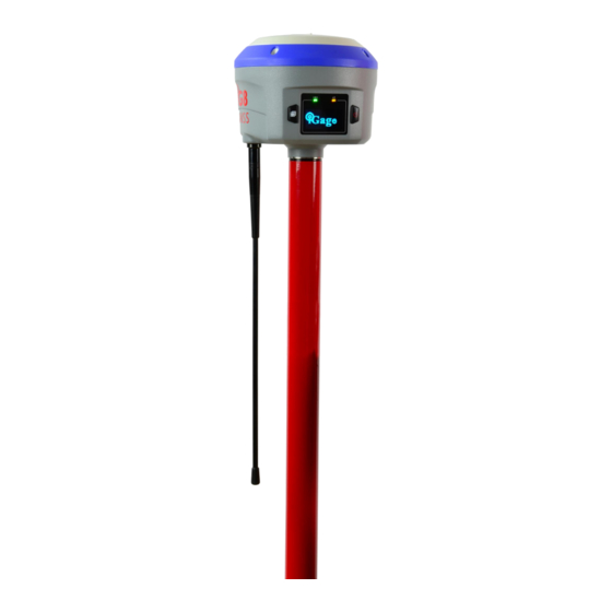
The iG8 GNSS receiver incorporates a GNSS engine, GNSS antenna, internal Satel UHF radio, Cellular modem, Bluetooth, Wi-Fi, and dual-batteries in a ruggedized and miniature unit that is easy to use. All-in-One iG8 Base Rover kits include two, identical receivers for use as Base and Rover. -
Page 8: Receiver Back And Bottom
GSM SIM Card iG8 receivers either have a MICRO or a NANO sized Sim Card slot for GSM micro SIM Card (micro is the middle-sized card, NANO is the smallest sized slot.) Insert with gold contacts up and notch leading. If your iG8 has a MICRO sized... - Page 9 Depending on your purchased configuration you will receive different accessories with your iG8 GNSS receivers: iG8 GNSS Receiver The iG8 receiver includes an state of the art GNSS engine, a Satel UHF radio, a 3.75G cellular GSM modem, Bluetooth, and Display.
- Page 10 Used to connect the receiver to a PC and download occupations from the internal memory. Included with [Rover] Extension Pole Raises the base iG8 GNSS head above a tribrach high enough to allow the UHF antenna to be connected to the receiver. Included with [Base] TNC Extension Cable...
-
Page 11: Safety Information
Use and Care The iG8 receiver is a field ready instrument; however it is also a delicate electronic instrument. Take suitable care to avoid damage to the instrument. -
Page 12: Battery Charger
It is okay to leave charged batteries in the charger for extended periods of time. Radio Notices FCC Notice: iG8+ GNSS receivers comply with the limits for a Class B digital device, pursuant to the Part 15 of the FCC rules when it is used in the Portable Mode. -
Page 13: Medical Devices - Pacemakers
FCC Licensing Information The iG8 includes transmit – receive UHF radios and require FCC licensure for transmit operation in the United States. It is illegal to operate the iG8 device in Transmit mode (as a UHF Base) without a valid FCC license. -
Page 14: Front Panel Operation
Most users never need to use the front panel controls so you can safely skip this section. Main Menu After the iG8 starts, the Main Menu will be shown SV:1 4 A uto 10 0% Mode Ro ver UH F Stat ic Off No t Re cord ing Rece ive r I nfo . -
Page 15: Base Info
That are only selected by a Bluetooth or Wi-Fi attached data collector. Mode Base Cable Highlight Base Ca ble Then click Enter to set the receiver as a base sending corrections out the hardware serial port. Select Format iGage iG8 User Manual... -
Page 16: Mode Base Int. Uhf
APIS server to get corrections. You can configure the following items for an APIS Base: Form at CMR IP 2 11. 144 .12 0. 97 Port 99 01 Canc el Highlight Format to toggle through CMR, CMR+, sCMRx, RTCMv2, RTCMv3, RTCMv3.2, sCMRx with the Enter key. Highlight ‘IP…’ iGage iG8 User Manual... -
Page 17: Mode Rover Apis
IP address. Available Ports: 9901, 9902 … 9920. Highlight the line then click Enter to choose the desired port. Mode Rover NTRIP/IP To connect the receiver to the last configured NTRIP/IP (IP = Direct IP) server, highlight iGage iG8 User Manual... -
Page 18: Mode Rover Uhf
Cancel and click Enter to return to the Mode menu without making any changes. Note: the iG8 receiver will automatically detect the correction format (CMR, CMR+, RTCM2, RTCM3, RTCM3.2, sCMRx) and no protocol selection is required for an iG8 rover. -
Page 19: Receiver Info
Data Format line and press Enter to toggle through HCN (default), HRC and Off. HCN must be selected to use the iGage iGx Downlaod tool to automatically submit jobs to OPUS. Highlight the RINEX Format and click Enter to toggle through 2.11, 3,02 and... -
Page 20: Using Survce To Control The Ig8
SurvPC running on a stand-alone tablet computer. The iG8 will work with SurvCE Version 5.08 or higher. We recommend SurvCE / SurvPC Version 6.05.04 or higher. Throughout this manual, it is assumed that you have a SurvCE job open on your data collector when you begin setting up Base and Rover configurations. - Page 21 The coordinate projection list will now include your The projection drop box displays a list of often used selected projection. projections. If the projection you need is not listed in the drop- down list click on Edit Projection List: iGage iG8 User Manual...
- Page 22 You may want to change the default Angle Entry and Display from Azimuth to Bearing: Bearing “N 45 12 52 W” Azimuth “315 12 52” Select the New Job options tab: Unless you setup at the same location for every job iGage iG8 User Manual...
- Page 23 NOT ContinentalUS_NGS2018.gsb. The version without the extra ‘_’ is an errant model. 15. Finally click the green check mark to return to the Main Menu. You are now ready to configure a Base or a Rover. iGage iG8 User Manual...
-
Page 24: Setting Up A Ig8 Uhf Base Rover Pair
Base Radio Battery iGage does not provide an external battery for use with the Base as they are difficult to safely ship and you can easily procured a suitable battery locally or online. Two internal batteries will run the iG8 Base for approximately 6 to 8 hours depending on the configured UHF output power. -
Page 25: Ig8 Base Configuration: Step By Step
Figure 6External Power Cable (optional) connected to serial cable for iG8 Base iG8 Base Configuration: Step by Step Additional Base Configuration information can be found on Page 57. If you are going to be working longer than Setup the Base:... - Page 26 After a moment, the ‘Current’ tab will be displayed: Wait up to 30-seconds while the data collector searches and identifies Bluetooth devices: Set the Manufacture to ‘iGage’ and the Model to ‘IG8’as shown above. Click on the ‘Comms’ tab: A list of nearby devices will be shown.
- Page 27 The only two choices that provide full corrections for all tracked satellites and signals are ‘sCMR’ and ‘RTCM3.2’. Choose ‘RTCM3.2’ if you are operating Check to insure that the correct antenna “IGAIG8…” with receivers that don’t support ‘sCMR’. Note that iGage iG8 User Manual...
- Page 28 14. The internal radio configuration is shown: 16. The Base Configuration screen is shown: iG8 pairs work great with the Base radio settings shown above. The Base and the Rover MUST have matching Protocol, Channel, Over the Air Baud, Forward Error Correction and Scrambling (if available.)
- Page 29 18. SurvCE will begin averaging GPS readings: A ‘Point ID’ of ‘1’ and a ‘Description’ of ‘BB’ (Broadcast Base) is reasonable. Click on the green check mark. 19. After 10-seconds, the average position will be shown: Click on ‘OK’. iGage iG8 User Manual...
-
Page 30: Best Practices For Extending Uhf Radio Range
Page 18. Best Practices for Extending UHF Radio Range The UHF radios in the iG8 have excellent range. However range is greatly reduced by other users on the same frequency, damaged antennas, damaged cables and configuration issues. -
Page 31: Base Output Power Setting
If the problem goes away, then you know that one (or perhaps both) of your original antenna have failed. Call iGage for ‘Original Equipment’ antennas (the black ones) and special extended range models. iGage iG8 User Manual... -
Page 32: External Antenna Extension (Top Of Pole Extension)
Bending out the ground contacts on the antenna connector. On the TNC connector, attached to the bottom of the GNSS receiver, bend the small gold fingers in to make better contact: Bending the center contacts in towards the center. iGage iG8 User Manual... -
Page 33: Configuring An Ig8 Uhf Rover
Mobile’, then click on the Settings button (hammer/wrench) button to the right of ‘BT Type’. The Bluetooth Devices menu is shown: Then click on ‘3 GPS Rover’ Choose the correct Manufacturer ‘iGage’ and Model ‘iG8’: If your receiver is not listed, click on ‘Find Device’ iGage... - Page 34 10. The Receiver configuration tab is shown: Then (2) click on the green checkmark. Check to insure that the correct antenna ‘IGAIG8…’ Click on the Bluetooth Connect button, just to the is selected. left of the red-X: iGage iG8 User Manual...
- Page 35 Click on the green check mark to configure the Rover. Select ‘Device’ = ‘Internal UHF’. The ‘Message Type’ should match the selection made at the base. (If you don’t know the base setting, don’t worry about it—the rover will automatically figure it out.) iGage iG8 User Manual...
-
Page 36: Troubleshooting A Uhf Base / Rover Pair
Base Too Close to UHF Rover The receive radios in the iG8 are very sensitive. This is why they work well at long distances from the Base. If the rover is very near the Base (less than 20 feet), the receiver in the Rover may be ‘over saturated’ and not able to understand the Base. -
Page 37: Debugging Rover: Float, Dgps, Dgps, Auto
Base position is 100 meters distant from reading’ when setting up the base then your rover will never fix. If the Status is FIXED, then the front panel of the iG8 receiver: In other words: ‘the entered Base horizontal and vertical location must be within 100 meters of the true base position.’... -
Page 38: Status = 'Autonomous', 'Waas' Or 'Dgps
Dumping the receiver (turning upside down then right side up) may help. Raising the rod height may help. Waiting a while for a better satellite constellation may help. (See the Mission Planning section below.) iGage iG8 User Manual... - Page 39 LED flashing), do not waste of your time waiting for a FLOAT or FIX solution. Look for the reason that corrections are not active. A receiver that is not receiving corrections will never move to the FLOAT or FIX status. iGage iG8 User Manual...
-
Page 40: Mission Planning
Click on ‘Charts’ and roll down to the PDOP chart: GDOPs higher than 3 will present difficult operation, GDOPS higher than 5 may not fix under canopy. However, as you can see above waiting 20 minutes might make a huge difference. iGage iG8 User Manual... - Page 41 The Mission Planning tool is also available in a mobile version: iGage iG8 User Manual...
-
Page 42: Configuring An Ig8 Network Rover
=> <=> <=> Another connection method is to use the GSM cellular modem (Internal GSM) built into the iG8 head to connect to the network. This is a great connection method because: the data collector does not have to broker the correction stream with the network server ... -
Page 43: Connecting Your Data Collector To A Wi-Fi Hotspot
NOTE: Disconnect the USB cable from your PC to the data collector before setting up Wi-Fi. Wi-Fi will not coexist with a USB connection. When you plug the USB connection into your computer, the Wi-Fi connection is disabled. iGage iG8 User Manual... - Page 44 Make sure that Wi-Fi is enabled: Enter the network key (this is the secret passcode for your access point.) The passcode is case-sensitive and must be correct. Click on Next: Click on Menu: Wi-Fi Settings, Finally click on Finish: iGage iG8 User Manual...
-
Page 45: Nautix X8 Wi-Fi Setup
The data collector will show ‘Connecting’ for a while and (HTTPS) site (like www.igage.com) using the ‘Internet then switch to ‘Connected: Explorer’ on the data collector: If your data collector has successfully connected to the internet you should be able to browse to any non-secure Continue the Network Rover setup at “Network (NTRIP and DIP) Rover... - Page 46 YES.” If you know the passcode for your hotspot click on NO. (You will not see this item, if your access point does not have a WPS button.) iGage iG8 User Manual...
- Page 47 If you click on No (recommended) the password screen is Finally, start the internet explorer and browse to the igage shown: web site: (1) Enter your password in the PSK (Pre-Shared-Key) box, By typing in “igage”, then clicking on ‘www.igage.com’.
-
Page 48: Configuring The Ig8 Internal Cellular Modem
Configuring the iG8 Internal Cellular Modem Internal GSM Method: If you use the internal Cellular Modem in the iG8 receiver, you will need to insert an activated GSM sim card into the card slot in the battery compartment. Depending on the build date of your iG8, the slot will accept a micro or nano-sim cards (the middle sim card size or the smallest sim card size). -
Page 49: Network (Ntrip And Dip) Rover Configuration
Click on Dial to attempt to connect. After about 30 seconds, the Dialing Status will be ‘Connected’ when the iG8 is registered on the cellular network. Alternatively you can configure the Cellular modem with SurvCE when setting the iG8 as a network rover as described in the next section. - Page 50 After short wait, all of the Bluetooth devices in range of the data collector are listed: SurvCE will return to the Comms tab: Verify that the correct Rover device is selected. Then click on the Receiver tab. iGage iG8 User Manual...
-
Page 51: Choose Internet Data Source
You should have already installed a GSM SIM card as to a Wi-Fi hotspot as shown in the section ‘Connecting shown in the section ‘Configuring the iG8 Internal your Data Collector to a Wi-Fi Hotspot’ on page 43. Cellular Modem’... - Page 52 Wi-Fi (or internal modem’s) data connection. The most common provider settings are: AT&T Broadband APM = broadband iGage DAC USER APM = dac.com.attz (1) Select the ‘Provider’, then (2) click the Settings (hammer/wrench) button. iGage iG8 User Manual...
- Page 53 Supplied DAC Card: Set the APN Server to ‘dac.com.attz’, leave the APN User Name and APN Password blank. Click the green check mark. Click the green check mark again to save the APN settings Next choose a NTRIP or DIP server source. If you have an Address, IP Port, User Name and Password then the connection is probably ‘NTRIP’.
- Page 54 After a moment, you should see a list of ‘Mount Points’ for the RTK Network. Choose the best mount point for (1) Check the ‘Base ID’ then (2) click the green check mark to complete the DIP setup. iGage iG8 User Manual...
- Page 55 If shown DO NOT check the ‘Use server transformations’ check box!: This selection is available ONLY if the correction source is RTCM3 and should VERY rarely be used. Click the green check mark to return back to the RTK tab: iGage iG8 User Manual...
- Page 56 (1) verify the mount point and then (2) click the green checkmark to configure the iG8 NTRIP Network Rover and connect to the selected network source. 12. When the network rover setup is complete you will return to the Equip menu: The receiver status will be FIXED if the connection was made, you are in the open.
-
Page 57: Advanced Base Configuration
HI (which may need to be derived would just work. In fact, this is exactly how the ‘Use Local from a slant measurement) and the L1 offset (determined Coordinates’ button works. by the antenna model) which describes the offset from iGage iG8 User Manual... -
Page 58: Double Check Your Base Position
Rover will be extremely slow fixing. Your rover will not report stable positions and your field day will be miserable. The control point that you have selected has the WRONG elevation. You need to fix it. First click ‘Read From GPS’. iGage iG8 User Manual... -
Page 59: Starting A Base With Local Coordinates
RTK tabs normally. The ‘Base Configuration’ tab is shown. Select the ‘From Known Position’: Click on the green check mark. SurvCE will read the current Latitude, Longitude, Ellipsoid Height position from the base. (In the USA this position iGage iG8 User Manual... - Page 60 Click on the green check mark to return to the Equip tab. SurvCE will ask if you would like to reprocess the Raw File: The .REF file contains the Latitude, Longitude and Ellipsoid Height of the Ground Mark. You will need this iGage iG8 User Manual...
-
Page 61: What Is Happening In The Background
Longitude, Ellipsoid Height) very close to its TRUE position: SurvCE will recalculate any previously stored points: SurvCE automatically set up a single point localization in the background. You can view it by going to “Equip: Localization: Points”: iGage iG8 User Manual... -
Page 62: How Do I Setup On The Same Base Point On A Subsequent Day
The HI does not need to match. Start the Base: Equip (tab), GPS Base: then enter the correct HI on the Select the same reference file (1) that you saved on the first day, then (2) click the green check mark. iGage iG8 User Manual... - Page 63 The base is reconfigured exactly as it was the first day. The effective Ground Mark elevation under the receiver is identical to the previous survey. Since you are still using the original job file, the correct localization is automatically used. iGage iG8 User Manual...
-
Page 64: What Happens In Survce's Raw File When You Configure A Gnss Base
In this example the base is on a fixed height 2-meter rod so the Antenna Height is: 2.0000 m = 6.5617 sFeet Vertical distance from GM to ARP After configuring the ‘RTK’ tab, and then doing a 10 point average, this is the ‘Base Configuration’ screen: iGage iG8 User Manual... -
Page 65: Ref File Description
This point matches the --GS line in the raw file. Note that the elevation is the orthometric height of the Ground Mark. After the base begins transmitting, the Base Info screen on the iG8 display displays the Phase Center with Ellipsoid Height in meters: B: 4 0:4 4:1 0.4 09 7... -
Page 66: Rw5 File Description
Phase Center: broadcast coordinate is for PC A --GS comment record: Point ID Projected Northing Projected Easting Orthometric Elevation of the Ground Mark in job units Description ‘Base’ A – GT comment record (included if ‘Store GPS Accuracy’ is enabled) Point ID iGage iG8 User Manual... -
Page 67: Adjusting Data Stored With An Autonomous Base To An Opus Position
Combined Factor 0.99946031 0.99981805 The method for entering a new point, #2 differs depending on if the projection (the coordinate system) is the State Plane projection returned in the OPUS solution, or a Localized Coordinate System: iGage iG8 User Manual... - Page 68 ‘m’ after the metric ellipsoid height: Do the same for the Easting and Orthometric elevation, don’t forget to enter a ‘m’ after each metric value: Click the ‘Solve N/E’ button on the right, then enter 2 in the ‘Pt ID:’ box:’ iGage iG8 User Manual...
- Page 69 Go to the ‘COGO: 7 Transformation’ tool from the main differences from the OPUS result to the autonomous menu. Enter the ‘Original Point ID:’ as ‘1’ and the base: ‘Destination Point ID’ as ‘2’: Click the red back button to return to the main menu. iGage iG8 User Manual...
- Page 70 SurveCE will verify the transformation: Click ‘Yes’. The adjustment will be completed and the job coordinates will be modified to match the OPUS solution. You can verify that it was successful by returning to the ‘File: Points’ list: iGage iG8 User Manual...
-
Page 71: Connecting The Ig8 To A Pc Or Smartphone Via Wi-Fi
Connecting the iG8 to a PC or Smartphone via Wi-Fi The iG8 receiver has an internal Wi-Fi Access Point which can be used in conjunction with a PC or smartphone to setup and control every feature of the receiver. First make sure that the Wi-Fi hotspot in the iG8 is turned on. -
Page 72: Using Hcconfig Via Wi-Fi Or Serial Port
You can download the latest version of HcConfig from this Tools link on the iG8 website: www.iG8g.com Download the latest build (the version with the highest ending number.) Build 1196 or higher is required for the iG8. HcConfig by Serial Port Connect your computer’s serial port to the 9-pin serial cable connected to the serial port on the iG8:... - Page 73 Click the ‘Connect’ button: Many of the receiver settings can be configured from the Main Menu: iGage iG8 User Manual...
-
Page 74: Programming Ig8 Radio Frequencies And Fcc
With this tool you can create a standard list, modify frequencies, move frequencies up/down. When the frequency list matches your FCC License, then you can save a .CFG file for uploading to the iG8 receiver. You must login to the GPS receiver using the instructions ‘Connecting the iG8 to a PC with... -
Page 75: Using The Imu (Tilt And Direction) Sensors
Using the IMU (Tilt and Direction) Sensors The iG8 receiver has an internal IMU: tilt sensors (an electronic bubble) and an electronic compass. The IMU can be used to check the pole level, store the pole level in the RAW file and optionally correct for pole tilt (Tilt Compensated Shots.) NOTE: Tilt compensated shots are currently not supported by the iG8, the accuracy and suitability for any purpose is not warranted. - Page 76 10. The display will show the live results of the the green check mark. calibration 14. The store and stake screens will now include concentric level circles: 11. Click the red back button to return to the GPS Utilities menu. iGage iG8 User Manual...
-
Page 77: Setting Up The Optional Adl Vantage Pro Repeater Kit
Large deep cycle marine batteries with screw terminals that will directly accept the lug connectors of the supplied cables are available at reasonable cost from many local sources. iGage typically does not provide an external battery for use with the repeater. -
Page 78: Setting Up The Repeater
Prism pole through tripod head Figure 12 UHF Repeater Configuration Mounting the antenna as high as possible will result in better radio range. Doubling the height of the antenna is much more effective than quadrupling the output power. iGage iG8 User Manual... - Page 79 UHF antenna to the North of the GNSS base. (There are very few SV’s to the North of your GNSS receiver NOTE: If you change a value, be sure to press the so the impact is minimized.) center Enter button to store the change. iGage iG8 User Manual...
- Page 80 The correct value is 9600. 17. Press the ‘right-arrow’ to skip Signal Strength: 12. Set the Repeater Mode to ‘ON’: 13. Set the RX Sensitivity (for the base) to High. This allows the repeater to easily hear the base iGage iG8 User Manual...
- Page 81 26. One last right click and you are back to the Device Enabling Scrambling lengthens each data packet. Status: 22. Set FEC (Forward Error Correction) to ‘OFF’ (this setting must match the setting on the Base and Rover): Turning FEC ON lengthens each data packet. iGage iG8 User Manual...
- Page 82 31. This screen indicates if the transmitter is enabled and what the output power is: Always leave this setting as shown. Always leave this setting as shown. Do not be concerned that it lists countries that do not include the USA. iGage iG8 User Manual...
- Page 83 User Manual...
-
Page 84: Dealer Programming The Adl Vantage Pro Or 35 Radio
(by clicking Connect) and re-read the radio configuration after checking ‘Allow Uncommon Modes’. Select 'SATEL, EC Off, FEC Off' which is the default Satel / 3AS mode used for iGage iG and CHC receivers. CSMA should be checked for legal operation in the USA unless you have a dedicated, unshared channel. Set the Sensitivity to Medium to keep low power noise from throttling the repeater’s output. -
Page 85: Serial Interface (Tab)
It is illegal to program a radio with unlicensed frequencies. It is illegal to program a radio to 25 KHz unless your FCC license allows 25 Khz operation. In addition to simplex channels (the Rx and Tx frequencies are the same) you may want to program some cross channel pairs like: Rx 461.025 Tx 464.700. iGage iG8 User Manual... -
Page 86: Backing Up Carlson Jobs: Never Loose Data In Survce
Once the folder is named, click on the ‘Copy Crt (current) Job to Storage’. It will take about 1/2 second to replicate all of the current job’s files in the backup location. Throughout the day return to this menu and click the ‘Copy Crt…’ button again to freshen your backup data copy. iGage iG8 User Manual... -
Page 87: Data Collectors Should Never Standby & Manually Reconnecting
If the automatic reconnect does not work (and this can happen often), you can manually ask SurvCE to reconnect to the RTK head. This is very useful after changing the battery mid-day. From the main SurvCE menu click on the ‘Hard Hat’ in the upper left corner, then click on ‘Reconnect’: iGage iG8 User Manual... - Page 88 SurvCE will re-initialize the Bluetooth communication link between the data collector and the RTK head. If the Reconnect selection fails to reestablish the connection, reconfigure the rover from ‘Equip: GPS Rover’. iGage iG8 User Manual...
-
Page 89: Connect To Every Wi-Fi Access Point, Not
Connect to Every Wi-Fi Access Point, NOT! Before you use your iG8 GNSS receiver in a network environment with a Wi-Fi based source of corrections, take a moment to disable automatic hotspot tracking. One of the annoying features of Windows CE and Windows Embedded is the automatic suggestion that you connect to every Wi-Fi hotspot that you pass by while surveying. -
Page 90: Connecting Data Collector By Bluetooth To Pc 'Windows Mobile Device Center
(1) on the top bar, then click on ‘Wireless Manager’ (2): then ‘Bluetooth Settings’ The Bluetooth Settings screen will be shown: The Wireless Manger is shown, if Bluetooth is off click on the big blue Bluetooth bar to toggle Bluetooth on: iGage iG8 User Manual... - Page 91 11. On the mobile device, navigate to the Bluetooth On the mobile device, you will be prompted to pair: Settings dialog: Click on ‘Yes’. Click-and-hold on your computer name (my Your PC will display a secret passcode: computer’s name is ‘MARK13’) iGage iG8 User Manual...
- Page 92 13. Now, on your PC you will see ‘connecting’: After 30 seconds your device will be active-synced to your PC. The connection is fast and it will be remembered, so it will be easy to setup in the future. Click on Connect. iGage iG8 User Manual...
-
Page 93: Downloading, Processing And Archiving Static Data
Using the Download Tool computer. Assuming the iG8 GNSS receiver is plugged in and has You can always get the latest version of the iGx mounted as a drive letter, just press the 'Download... -
Page 94: Submitting An Occupation To Opus
If this is consistently incorrect, you can modify the Settings’ is set to “Normal”, “Support OPUS-Projects” device type while it is connected on the ‘Configuration’ or “Advanced” then this ‘RINEX Solution’ helper screen tab. is shown: iGage iG8 User Manual... -
Page 95: Viewing The Observation Log
Only the submitted file is trimmed, all of the original data remains in the occupation. The trim settings must be reloaded after each submission. Performing Quality Control Checks (Hidden when Simple) iGage iG8 User Manual... -
Page 96: Base Project Folder
Note: If you manually delete every single file and about HI blunders. folder from the GPS receiver, the program won't FEET: If you measure up in feet, you can enter the height in decimal feet and put an 'F' after the iGage iG8 User Manual... -
Page 97: Default Agency
Where 1005 is the Point ID, 072 is the Julian date, 0 is 'Show Advanced Settings' the observation number, 14 is the year and O indicates an observation file. Format Extended (Only shown when PPP Service = OPUS) This setting determines the complexity of the X9x- Download program. iGage iG8 User Manual... -
Page 98: Utilities
“2. HcRINEX Convertor” The GPS Settings options on the download tool are not compatible with the iG8. You can use the front panel Files are stored on the receiver in an ‘.HCN’ binary file. controls or the Wi-Fi connection to make interval When the tool downloads a file, it is automatically changes to the iG8. -
Page 99: Opus-Rs (Rapid Static)
Lat / Lon RMS < 0.030(m) and multiple sessions. If you collect data under canopy or in an area where there are buildings or trees that obstruct the view iGage iG8 User Manual... -
Page 100: Survey Feet Vs. International Feet, Scale Factors
‘Static’ availability. Height verified? OPUS-Rapid Static Requirements Tripods / Bipods / Tribrach / Tribrach adaptors: tribrach calibrated? Find the closest 9 CORS sites with Tools for adjusting bubbles (the correct available observations Allen wrenches) iGage iG8 User Manual... -
Page 101: Using Opus-Projects
‘OPUS-Projects’), the Download tool form and fill in the project identifier: can assist you when uploading files: 1. Turn ON OPUS-Projects support. On the ‘Configuration’ tab, set ‘Show Advanced Settings’ to “Support OPUS-Projects”: iGage iG8 User Manual... -
Page 102: Troubleshooting The Ig8 Receiver
Troubleshooting the iG8 Receiver 1. Receiver won’t turn on: Battery is fully discharged: Charge battery or use external power. Contacts on battery are dirty: Clean battery and receiver contacts with a soft cloth or soft eraser. Battery is bad: Try another battery. -
Page 103: Ig8 Serial And Usb Io Port Definitions
Ground ( -) Ground ( -) RS232-TX (Output) PPS (Pulse Output) Not Used RS232-RX (Input) Figure 14 iG8 7-Pin Serial IO Lemo Connection Information USB Port Definition The iG8 has a standard USB-Mini connector. Name Wire color Description +5 V D−... -
Page 104: Upgrading Firmware With The Otg Cable
Upgrading Firmware with the OTG Cable Note: You can also upgrade the device using a Wi-Fi connection using a web browser. Figure 15 updating the iG8 Firmware with the OTG Cable Copy the firmware file (xxx.bin file) to the root directory of a thumbdrive. -
Page 105: Gnss Reset
GNSS Reset It is possible to reset the iG8 from the Front Panel and from the web interface. This procedure should not be required for normal operation. Web Interface Reset Connect your PC or smartphone to the iG8 receiver as shown in ‘Connecting the iG8 to a PC with Wi-Fi’ on page 71. -
Page 106: Ig8 Antenna Model
Antenna Model The iG8 receiver has a robotic type mean antenna calibration performed by Geo++ GmbH. The .atx and .gra files for the iG8 can be found on the website https://iG8g.com Summary 114.0 mm 91.07 mm Radius 67.7 mm SHMP 83.9 mm... -
Page 107: Slant Height' To 'Vertical Height
‘Slant Height’ to ‘Vertical Height’: Manually Converting Heights Receiver Radius SHMP r (meters) h (meters) 0.0677 0.0839 �� = √ s − r − h Examples Measured Slant s Slant s (feet) Vertical v 6.965 2.123 2.0380 5.148 1.569 1.4837 iGage iG8 User Manual... -
Page 108: Warranty
IMC is “iGage Mapping Corporation” of Salt Lake City Utah USA. IMC warrants the iG8 receivers, which we sell, to be free of defects in material and workmanship and will conform to our published specifications for these periods:... -
Page 109: Rma
To obtain warranty service from iGage Mapping Corporation the purchaser must obtain a return materials authorization (RMA) number prior to shipping by calling +1-801-412-0011 Or by email: info@igage.com Purchaser’s return address and the RMA number must be clearly printed on the outside of the package. IMC reserves the right to refuse to provide free-of-charge service if the date of sale cannot be determined or if the serial number is altered or removed.
Need help?
Do you have a question about the iG8 and is the answer not in the manual?
Questions and answers