sparkfun ESP8266 Hook-Up Manual
Wifi ir blaster
Hide thumbs
Also See for ESP8266:
- Hook-up manual (24 pages) ,
- Manual (33 pages) ,
- Hook-up manual (16 pages)
Table of Contents
Advertisement
Quick Links
SparkFun WiFi IR Blaster Hookup Guide
Introduction
Note: Please note that this tutorial is for WRL-15031. If you are using SPX-15000, please refer to this
tutorial.
With the advent of WiFi-connected "smart" devices, IR remotes are quickly becoming a thing of the past. Why sort
through a coffee table-full of remotes when you probably have a much smarter, WiFi-connected device device
sitting conveniently in your hand?
The WiFi IR Blaster is designed to connect all of those old, legacy IR-controlled devices to a WiFi network –
exposing them to a new method of control. Want to control your TV via a web-browser? Want to ask Alexa to mute
your stereo? Want to schedule triggers to your IR-controlled LED strip? These are all applications that the WiFi IR
Blaster is perfect for.
SparkFun WiFi IR Blaster (ESP8266)
WRL-15031
Advertisement
Table of Contents

Subscribe to Our Youtube Channel
Related Manuals for sparkfun ESP8266


Summary of Contents for sparkfun ESP8266
- Page 1 SparkFun WiFi IR Blaster Hookup Guide Introduction Note: Please note that this tutorial is for WRL-15031. If you are using SPX-15000, please refer to this tutorial. With the advent of WiFi-connected “smart” devices, IR remotes are quickly becoming a thing of the past. Why sort...
-
Page 2: Required Materials
MQTT, TCP, etc. and infrared-controlled devices. This tutorial will explain how to assemble the WiFi IR Blaster and it will detail how to program the ESP8266 using the Arduino IDE. Once complete, you’ll have a simple web server than can emit infrared signals at the click of a browser-page. -
Page 3: Suggested Reading
In addition to those components, you’ll need a soldering iron, solder, and general soldering accessories. To add, you’ll also need a local WiFi network that you can connect your ESP8266 up to. It also helps to have a second device – smartphone or computer – that’s also connected to that network. -
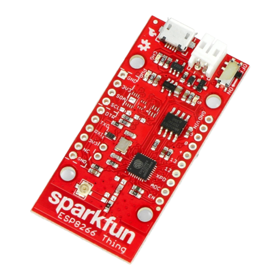
Page 4: Hardware Overview
SparkFun logo, so try not to place anything that may interfere with WiFi signals near that area. Supporting the ESP8266 are a reset and general purpose button, a user LED, and an array of pin breakouts. Of course, there’s also the IR emitter and detector. These components are packaged with the board, but not soldered in place. -
Page 5: Assembly Tips
The IR emitter is a Lite-ON LTE-302. It’s driven by an NPN transistor, which helps amplify the current through the LED. The IR receiver is a TSOP38238. This is a simple IR receiver hard-coded to receive IR signals modulated at 38kHz. - Page 6 6V. To use this regulator, connect your power source to the VIN pin. Alternatively, a pair of 3.3V pins are broken out on both headers. This pin directly supplies the ESP8266, so it should remain regulated to the range of ESP8266: 3.0V-3.6V.
- Page 7 The board definitions can be found in the ESP8266 Arduino GitHub repository. For installation instructions, check out this section of the README. The WiFi Blaster board definition is not included with the Arduino ESP8266 board files, but it can be uploaded to as a Generic ESP8266 Module. Verify your settings look like below:...
-
Page 8: Testing The Receiver
Auto vs. Manual Reset Into Bootloader In addition to the RX and TX pins, the FTDI’s DTR pin is used to reset the ESP8266 and get it into bootloader mode. The board includes circuitry to automatically reset and bootload the board; in most cases, you shouldn’t have to do anything special to program it. - Page 9 IR signals. To test out the receiver, open up the IRrecvDumpV2 example by navigating to the File > Examples > Examples from Custom Libraries > IRremoteESP8266 menu. Before uploading the sketch, you need to modify the pin definition on line 39. This sets the ESP8266 RECV_PIN pin connected to your IR receiver. Set it to 13.
- Page 10 One last example which really begins to show the power of this module is the IRServer example. This sketch will connect your ESP8266 to WiFi and set it up as a web server. When the right HTTP endpoint is hit, it will send a desired command.
- Page 11 Exploring the IRRemoteESP8266 library is just the very tip of this WiFi IR Blaster iceberg. We highly recommend checking out the IR Controller ESP8266 firmware. This fully featured firmware combines IR send and receive functions with a web server. It monitors for received commands, and provides a handy interface to emit those back out with the ESP8266.
- Page 12 Hardware Schematic – PDF schematic Eagle Files – PCB design files ESP-12S Datasheet – ESP8266 module w/ integrated crystal, antenna, flash LTE-302 Datasheet – IR emitter TSOP382 Datasheet – IR receiver Firmware IRremoteESP8266 Arduino Library – ESP8266 IR Arduino library ESP8266 IR Controller Firmware –...
- Page 13 Roshamglo Project: TV-B-Gone Turn your Roshamglo board into a (nearly) universal TV power button. AVC Sensor Test JUNE 20, 2016...
Need help?
Do you have a question about the ESP8266 and is the answer not in the manual?
Questions and answers