sparkfun ESP8266 Manual
Hide thumbs
Also See for ESP8266:
- Hook-up manual (24 pages) ,
- Hook-up manual (16 pages) ,
- Hook-up manual (13 pages)
Table of Contents
Advertisement
Quick Links
P
S
S
Introduction
i
h
h
Over the past year, the ESP8266 has been a growing star among IoT or WiFi-related projects.
n
a
a
It's an extremely cost-effective WiFi module, that – with a little extra effort – can be
r
r
programmed just like any microcontroller. Unfortunately, the ESP8266 has mostly only been
I
e
e
available in a
tiny, modular
form, which, with limited I/O and a funky pin-out, can be difficult to
t
build a project around.
o
o
n
n
F
T
a
w
c
i
e
t
b
t
o
e
o
r
k
The original ESP8266 WiFi module. Great for piggybacking onto an Arduino, hard to build a
project around.
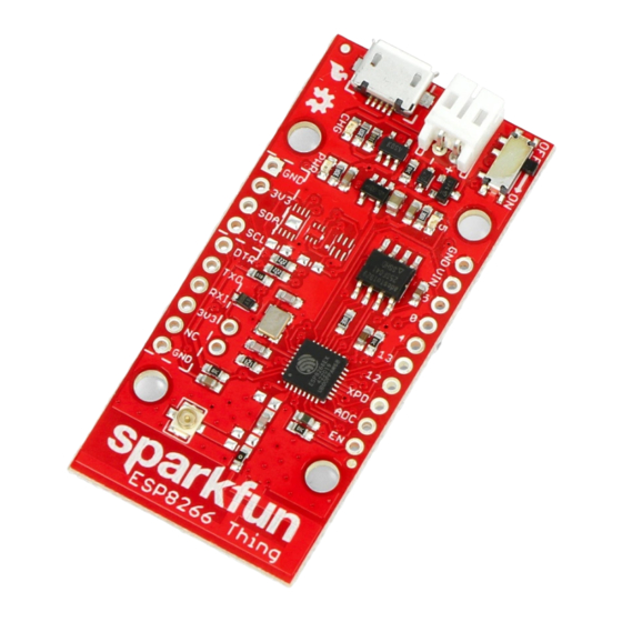
SparkFun's new development board for the ESP8266 breaks out all of the module's pins, and
comes equipped with a LiPo charger, power supply, and all of the other supporting circuitry it
requires. We lovingly call it
the Thing
– it's the perfect foundation for your Internet of Things.
Advertisement
Table of Contents

Related Manuals for sparkfun ESP8266


Summary of Contents for sparkfun ESP8266
- Page 1 Introduction Over the past year, the ESP8266 has been a growing star among IoT or WiFi-related projects. It’s an extremely cost-effective WiFi module, that – with a little extra effort – can be programmed just like any microcontroller. Unfortunately, the ESP8266 has mostly only been...
-
Page 2: Required Materials
Thing: ESP8266 Thing Hookup Guide SparkFun Wish List SparkFun ESP8266 Thing The SparkFun ESP8266 Thing is a breakout and development board for WRL-13231 the ESP8266 WiFi SoC – a leading platform for Internet of Things (IoT) or WiFi-re…... -
Page 3: Suggested Reading
Polymer Lithium Ion chemistry. This is the highest energy density currently in … VIEW ESP8266 THING HOOKUP GUIDE ON SPARKFUN.COM Suggested Reading Before continuing on with this tutorial, you may want to familiarize yourself with some of these topics if they’re unfamiliar to you:... - Page 4 Performs auto-reset, and puts the ESP8266 into bootloader mode. Connects through a capacitor to RESET, and a buffer to the ESP8266's GPIO0. ESP8266 UART1 data output. ESP8266 UART1 data input. By default, this pin does not supply the ESP8266 directly (a jumper on...
- Page 5 If you need the extra I/O, instead of I C, the SDA and SCL pins can be used as GPIO 2 and 14 respectively. The SCL pin also serves as the clock (SCLK) for the ESP8266’s SPI interface. General I/O Header The rest of the power, control, and I/O pins are broken out on the other side of the board.
- Page 6 Of these jumpers, the DTR one is the most commonly modified. The DTR output of the FTDI Basic is used for two purposes: to reset the ESP8266 and pull GPIO0 low (putting the chip in bootloader mode). Keeping this jumper closed enables programming, but makes debugging via the Serial Monitor difficult, as the board will reset into bootloader mode whenever the terminal opens.
-
Page 7: Selecting The Antenna
If you need to connect a more sensitive antenna to the chip, a U.FL connector is also available on the board, but isn’t connected by default to the ESP8266’s antenna pin. To connect this antenna to the chip, you’ll need to heat up the 0Ω resistor and rotate it 90°: An (ugly, uncleaned) resistor swapped from printed antenna to U.FL antenna. - Page 8 After a late change of heart, we decided to keep the board as low cost as possible (that’s the ESP8266’s best feature!), while leaving the option for later expansion. The pads are still there. If you want to add any of these components, hopefully all you should need is a...
-
Page 9: Electrical Characteristics
Electrical Characteristics The ESP8266’s maximum voltage is 3.6V, so the Thing has an onboard 3.3V regulator to deliver a safe, consistent voltage to the IC. That means the ESP8266’s I/O pins also run at 3.3V, you’ll need to level shift any 5V signals running into the IC. - Page 10 Programming the Thing The ESP8266 has a built-in serial bootloader, which allows for easy programming and re- programming. You don’t need a specialized, expensive programmer – just a simple, USB-to- Serial converter. We use a 3.3V FTDI Basic to program the Thing, but other serial converters with 3.3V I/O levels should work (e.g.
-
Page 11: Hardware Assembly
If you solder female headers to the Thing, plugging a 6-pin row of right-angle male headers between the FTDI and header helps create a temporary programming interface. Hardware Assembly Oh. We’re getting ahead of ourselves. To connect the FTDI programmer to your Thing you’ll need to solder something to the Thing. - Page 12 Or you can mix and match headers to best fit your needs. Right-angle male headers may help to interface between the FTDI and the Thing. Straight male headers are a good choice for low-profile connections. Straight female headers may help with connecting to I C sensors.
- Page 13 Arduino addon. If you’re just getting started programming the ESP8266, this is the environment we recommend beginning with, and the one we’ll document in this tutorial. This ESP8266 addon for Arduino is based on the amazing work by Ivan Grokhotkov and the rest of the ESP8266 community. Check out the...
- Page 14 Hit OK. Then navigate to the Board Manager by going to Tools > Boards > Boards Manager. There should be a couple new entries in addition to the standard Arduino boards. Look for esp8266. Click on that entry, then select Install.
- Page 15 The board definitions and tools for the ESP8266 Thing include a whole new set of gcc, g++, and other reasonably large, compiled binaries, so it may take a few minutes to download and install (the archived file is ~110MB). Once the installation has completed, an Arduino-blue “INSTALLED”...
- Page 16 Then select your FTDI’s port number under the Tools > Port menu. Upload Blink To verify that everything works, try uploading the old standard: Blink. Instead of blinking pin 13, like you may be used to though, toggle pin 5, which is attached to the onboard LED. COPY CODE #define ESP8266_LED 5 void setup()
- Page 17 LOW); delay(500); If the upload fails, first make sure the ESP8266 Thing is turned on – the red “PWR” LED should be illuminated. Faster Uploads! The serial upload speed defaults to 115200 bps, which is reliable, but can feel a bit slow.
- Page 18 WiFiSSD and WiFiPSK variables, setting them to the SSID and password of your WiFi network. The rest of the sketch should just work. COPY CODE // Include the ESP8266 WiFi library. (Works a lot like the// Arduino WiFi library.)#include <ESP8266WiFi.h>// Include the SparkFun Phant library.#include <Phant.h> //////////////////////// WiFi Definitions ////////////////////////const char WiFiSSID[] = "WiFi_Network";...
- Page 19 // to the stated [ssid], using the [passkey] as a WPA, WPA2, // or WEP passphrase. WiFi.begin(WiFiSSID, WiFiPSK); // Use the WiFi.status() function to check if the ESP8266 // is connected to a WiFi network. while (WiFi.status() != WL_CONNECTED) // Blink the LED digitalWrite(LED_PIN, ledStatus);...
- Page 20 // Add the four field/value pairs defined by our stream: phant.add("id", postedID); phant.add("analog", analogRead(ANALOG_PIN)); phant.add("digital", digitalRead(DIGITAL_PIN)); phant.add("time", millis()); // Now connect to data.sparkfun.com, and post our data: WiFiClient client; const int httpPort = 80; if (!client.connect(PhantHost, httpPort)) // If we fail to connect, return 0.
- Page 21 Example Sketch: AP Web Server Not only can the ESP8266 connect to a WiFi network and interact with the Internet, but it can also set up a network of its own, allowing other devices to connect directly to it. This example demonstrates how to turn the ESP8266 into an access point (AP), and serve up web pages to any connected client.
- Page 22 // Check if a client has connected WiFiClient client = server.available(); if (!client) { return; // Read the first line of the request String req = client.readStringUntil('\r'); Serial.println(req); client.flush(); // Match the request int val = -1; // We'll use 'val' to keep track of both the // request type (read/set) and value if set.
- Page 23 WiFi.softAPmacAddress(mac); String macID = String(mac[WL_MAC_ADDR_LENGTH - 2], HEX) + String(mac[WL_MAC_ADDR_LENGTH - 1], HEX); macID.toUpperCase(); String AP_NameString = "ESP8266 Thing " + macID; char AP_NameChar[AP_NameString.length() + 1]; memset(AP_NameChar, 0, AP_NameString.length() + 1); for (int i=0; i<AP_NameString.length(); i++) AP_NameChar[i] = AP_NameString.charAt(i);...
- Page 24 The sketch sets the network’s password to “sparkfun”. After connecting to your Thing’s AP network, load up a browser and point it to 192.168.4.1/read. The Thing should serve up a web page showing you its ADC and digital pin 12 readings: After that, give 192.168.4.1/led/0 and 192.168.4.1/led/1 a try, and keep an eye on the Thing’s...
- Page 25 Make sure you disconnect the two pins before trying to upload a sketch. After you tell the ESP8266 to sleep, it’ll wait a specified number of microseconds, then trigger the XPD pin to toggle the reset line. When the ESP8266 wakes up, it’ll begin back at the start of the sketch.
- Page 26 // to the stated [ssid], using the [passkey] as a WPA, WPA2, // or WEP passphrase. WiFi.begin(WiFiSSID, WiFiPSK); // Use the WiFi.status() function to check if the ESP8266 // is connected to a WiFi network. while (WiFi.status() != WL_CONNECTED) // Blink the LED digitalWrite(LED_PIN, ledStatus);...
- Page 27 // Add the four field/value pairs defined by our stream: phant.add("id", postedID); phant.add("analog", analogRead(ANALOG_PIN)); phant.add("digital", digitalRead(DIGITAL_PIN)); phant.add("time", millis()); // Now connect to data.sparkfun.com, and post our data: WiFiClient client; const int httpPort = 80; if (!client.connect(PhantHost, httpPort)) // If we fail to connect, return 0.
- Page 28 30 seconds. But there’s one huge difference: sleep. Notice there’s nothing in the loop(). The program halts when the ESP.deepSleep(30000000) is called. After 30 seconds, when the ESP8266 wakes up, it’ll start running code back at the beginning of setup().
- Page 29 // Print button pressed message. ESP8266WiFi Class This is the ESP8266, so the WiFi class will probably be included in just about every sketch there is. If you’ve used the Arduino WiFi library before, the ESP8266 WiFi library will be very similar, there’s just a few key differences:...
-
Page 30: Number Function
LOW (0V) Bootloader To make it easy to program the ESP8266, we’ve tied GPIO0 to DTR (along with RST). When your programmer begins to upload a sketch, it’ll pull DTR low, in turn setting GPIO0 low and making the ESP8266 enter bootloader mode. - Page 31 Or you can find a serial terminal program that allows control of the DTR pin directly. RealTerm allows for this control – navigate to the “Pins” tab, and click “Clear” next to “DTR.”...
- Page 32 LED’s are for, right? (Tongue only kind-of in cheek.) Resources & Going Further An astoundingly awesome community has grown around the ESP8266. We owe them big time for the amazing Arduino addon they’ve cooperatively built. For all of your ESP8266 needs, we recommend checking out the esp8266.com Community Forum.
-
Page 33: Going Further
– Espressif is also somewhat active on GitHub. They host a • couple versions of the SDK here. The ESP8266 Thing is open source hardware! If you need, or just want to look at, the PCB design files, you can find them in our ESP8266 Thing GitHub repository.
Need help?
Do you have a question about the ESP8266 and is the answer not in the manual?
Questions and answers