Table of Contents
Advertisement
Quick Links
INSTRUCTION MANUAL
IMPORTANT: Read This Instruction Manual Completely before operating this equipment. Save this
manual and keep it handy for quick reference. Pay particular attention to the hazards and safety
precautions provided for your protection and for the protection of those in the immediate vicinity
where this device is to be used. Contact your distributor if you do not fully understand this
manual or require additional information.
Advertisement
Table of Contents

Related Manuals for GWS MIG200


Summary of Contents for GWS MIG200
- Page 1 INSTRUCTION MANUAL IMPORTANT: Read This Instruction Manual Completely before operating this equipment. Save this manual and keep it handy for quick reference. Pay particular attention to the hazards and safety precautions provided for your protection and for the protection of those in the immediate vicinity where this device is to be used.
-
Page 2: Table Of Contents
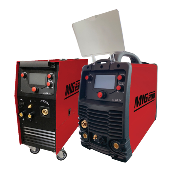
• The MIG250 runs 2X Drive Rollers & 2X Pressure Rollers 4.3 Argon ARC Welding Operation......11 • The MIG200 is a light weight, portable 17.6kg design 4.3.1 TIG Welding (4T Operation) ....... 11 • Excellent results on MG-11 Gasless wires 4.3.2 TIG Welding (2T operation)........ -
Page 3: Recommended Safety Precautions
IMPORTANT! Hot or moving parts can 150 to 250 amps Shade 10 cause serious injury and electric shock can kill. Use the following MIG200/250 operation guidelines to insure your 250 to 300 Shade 11/12 own personal safety and for those in the immediate vicinity... - Page 4 ROTATING PARTS MAY BE DANGEOUS: • Use suitable clothing made from durable flame-resistant material to protect your skin and that of your helpers from • Use only compressed gas cylinders containing the correct the arc rays. shielding gas for the process used and properly operating regulators designed for the gas and pressure used.
-
Page 5: Electrical Shocks
1.4 User Responsibilities satisfy all kinds of welding. • Read the Instructional Manual prior to using your The MIG200/250 are suitable for all positions welding for MIG200/250 various plates made of stainless steel, carbon steel, alloyed steel, aluminium, etc, which is also applied to pipe install- •... -
Page 6: Working Principle
2.1 Working Principle 2.2 Volt-Ampere Characteristic MIG200/250 Series welders have an excellent volt-ampere The working principle of MIG200/250 welders is shown as characteristic, displayed in the following graph. The relation the following figure. between the conventional rated loading voltage U... -
Page 7: Installation And Adjustment
The letter “X” stands for duty cycle, which is defined as the The relation of the welding current and proportion of the time that a machine can work continuously duty cycle for MIG200 within a certain time (10 minutes). 100%... -
Page 8: Movement And Placement
3.4 Power supply input connection The MIG200/250 welding machines’ power supply connects to 220V. When the power supply voltage is over/under the safe work voltage, the over voltage or under voltage protection inside the welder will trigger, turning the alarm light on and cutting the current output off. -
Page 9: Operation
• The workpiece is connected to the positive electrode of the welding machine, with the welding torch connected to the negative electrode, called the DC positive connection. Otherwise, it’s called the DC Negative connection. Generally it is usually operated as a DC positive connection when TIG welding. •... -
Page 10: Control Panel
4.2 Control Panel §4.2 Control panel LCD Display Current & Voltage/downslope wire /arc force adjusting feeding speed knob adjusting knob Inductance adjusting knob Main Control knob Overview The key feature of the control panel is the logical way in which the controls are arranged. All the main parameters are needed for day-to-day working can easily be: •... - Page 11 Setting welding ARC force current Weld Way Diameter Thickness electrode Display the setting Setting arc current force The actual current and voltage display (3) The Control Knob This knob is mainly used for navigating and confirming selections. When shifting the button left or right, the corresponding page will navigate to the left or right.
-
Page 12: Argon Arc Welding Operation
(4) The adjustment button for voltage, down slope and arc force In different welding states, this knob has differing functions: (1) In the mode of MMA, it can adjust the arc force, the range is 0~10; (2) In the mode of TIG, it can adjust the time of down slope; (3) In the mode of MIG, it can adjust the welding voltage, the range is 10~25V (5) The knob of inductance This button is used for adjusting the output inductance, the range is 1~10, used to make the... -
Page 13: Tig Welding (2T Operation)
• t3~t4: Welding process. During this period, the gun switch is loosened • t4: Repress down the gun switch, the output current slopes down to crater current • t4~t5: Down slope time, adjustment range of down slope time: 0~10.0S • t5~t6: Crater current holds time; adjustment range of crater current: 10~200A •... -
Page 14: Welding Parameters
Notices: • Check the condition of welding and connection units first, otherwise there may be malfunctions such as ignition sparks, gas leakages, loss of control and so on. • Check whether there is enough Argon gas in the shield gas cylinder, you can test the electromagnetic gas valve via the switch on the front panel. - Page 15 DC Positive Connection Welding current range/A Gas Nozzle Diameter/mm Gas Flow Rate/L · min 10~100 4~9.5 101~150 4~9.5 151~200 6~13 201~300 8~13 Electrode Diameter Diameter At Tip Constant Included Current Range Angle, Degrees .040 .125 .005 2-15 .250 .010 5-30 .040 1/16 .500...
-
Page 16: Operation Environment
Welding Piping Tungsten Argon Welding Welding Wire Gaas Nozzle Rate/ Diameter Electrode Flow Rate/ Current/A Diameter/MM Voltage/V Diameter/MM Φ/MM Diameter/MM cm · min L · min 75~90 11~13 11~13 75~95 75~100 11~13 8~10 8~10 80~105 14~16 9~11 8~10 90~110 14~16 10~12 8~10 90~115... -
Page 17: Troubleshooting
5.1 Troubleshooting If there are simple troubles with your MIG200/250 welding machine, you can consult the following overhauling chart: Troubles Reasons Solutions Light damaged or has a bad Test/repair the inside circuit of power When the machine is powered connection...
Need help?
Do you have a question about the MIG200 and is the answer not in the manual?
Questions and answers