Table of Contents
Advertisement
Quick Links
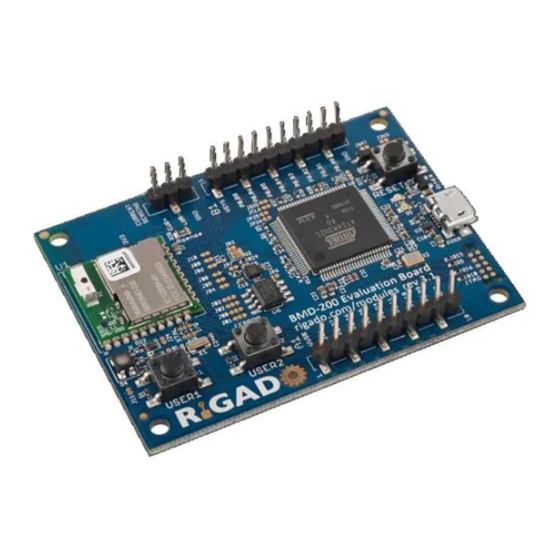
BMD-200 Evaluation Kit User Guide
This document describes the
This Evaluation Kit allows for stand-alone use of the
module featuring the Nordic nRF51822 RF System on Chip (SoC).
The purpose of this guide to provide setup instructions for starting
development and to describe the hardware functionality of the
BMD-200
Evaluation Kit.
1. Overview
The BMD-200 Evaluation Kit is a versatile hardware platform that provides an easy jumping off point for
almost any Bluetooth 4.1 Low Energy project. The kit can be powered externally via USB or with a CR2032
coin cell battery for portable use. USB provides a programming and debug interface (J-Link or CMSIS-DAP), as
well as communication via a virtual COM port. Two user configurable buttons are available, as well as an RGB
LED, ambient light sensor, accelerometer, EEPROM, and a current sense resistor. There is also an on-board
reset button. Breakout headers allow easy access to all of the BMD-200 GPIO pins.
1.1. Key Features
BMD-200 Bluetooth 4.1 System on Module (SoM)
On-board programming and debug (J-Link or Drag-&-Drop/CMSIS-DAP)
Virtual COM port over USB
Full GPIO pin out of BMD-200
I2C 3-axis accelerometer
Ambient light sensor
16kb SPI EEPROM
Buttons and LEDs for user interaction
32.768kHz Crystal
CR2032 battery holder
BMD-200-EVAL-UG-V1.4
Arrow.com.
Downloaded from
BMD-200
Evaluation Kit from Rigado.
BMD-200
(NXP
MMA8652FC)
(Avago
APDS-9005-020)
(ON Semi
CAT25160VI-GT3)
Rigado LLC
3950 Fairview Industrial Dr SE, Ste 100
Salem, Oregon 97302
866-6-RIGADO modules@rigado.com
www.rigado.com/modules
Page 1 of 20
Advertisement
Table of Contents

Related Manuals for RIGADO BMD-200-EVAL-S


Summary of Contents for RIGADO BMD-200-EVAL-S
-
Page 1: Overview
BMD-200 Evaluation Kit User Guide This document describes the BMD-200 Evaluation Kit from Rigado. This Evaluation Kit allows for stand-alone use of the BMD-200 module featuring the Nordic nRF51822 RF System on Chip (SoC). The purpose of this guide to provide setup instructions for starting... -
Page 2: Table Of Contents
BMD-200 Evaluation Kit User Guide August 10, 2016 Table of Contents 1. Overview ............................... 1 1.1. Key Features ............................1 1.2. Useful Tools ............................4 2. Hardware Kit ............................4 3. Getting Started ............................5 3.1. Evaluation Board with SEGGER J-Link ..................... 5 3.1.1. - Page 3 BMD-200 Evaluation Kit User Guide August 10, 2016 Figure 17 – GPIO Jumper Layout ........................17 Figure 18 – BMD-200 Evaluation Board Schematic ..................18 Figure 19 – BMD-200 Pin-out .......................... 19 BMD-200-EVAL-UG-V1.4 Page 3 of 20 Arrow.com. Arrow.com. Arrow.com. Downloaded from Downloaded from Downloaded from...
-
Page 4: Useful Tools
Windows serial port driver for mbed version of Evaluation Board. port driver 2. Hardware Kit The two different BMD-200 Evaluation kits contains each of the following: BMD-200-EVAL-S 1x BMD-200 Evaluation Board with on-board Segger JLink programmer 1x Micro-USB to USB-A cable BMD-200-EVAL-M... -
Page 5: Getting Started
This section walks through how to set up and program the BMD-200 Evaluation Kit. 3.1. Evaluation Board with SEGGER J-Link The BMD-200-Eval-S comes with a built in SEGGER J-Link programmer/debugger on board. 3.1.1. Set up tool chain 1. Download and install the latest Keil MDK-ARM development kit from www.keil.com/arm/mdk.asp... -
Page 6: Program Bmd-200 Evaluation Kit With The S130 Soft Device
BMD-200 Evaluation Kit User Guide August 10, 2016 3.1.3. Program BMD-200 Evaluation Kit with the S130 Soft Device 1. Open the Nordic nRFgo Studio application. In the ’Device Manager’ window, there will be a device named Segger followed by serial number under ‘nRF51 development boards.’ Select Segger and the device programming interface will appear in the main window 2. -
Page 7: Set Up The Application Project
BMD-200 Evaluation Kit User Guide August 10, 2016 3.1.4. Set up the Application Project 1. Navigate to the location of the extracted examples from the SDK (typically <unzipped location>\nRF5_SDK_11.0.0_89a8197\examples). 2. Select one of the examples that is labeled with “(nRF51 PCA10028)” and “s130”. The Heart Rate Service Sample Application ((<unzipped SDK location\ble_peripheral\ble_app_hrs\pca10028\s130\arm5_no_packs\) is a good place to start. -
Page 8: Figure 5 - Keil Flash Tools C/C++ Window
BMD-200 Evaluation Kit User Guide August 10, 2016 5. Go to the ‘C/C++’ tab, and in the field marked ‘Define’ change “BOARD_PCA10028” to “BOARD_CUSTOM” as shown in Figure 6. Figure 5 – Keil Flash Tools C/C++ Window 6. In the ‘Debug’ tab of the same ‘Options for Target’ window, select ‘J-LINK/J-TRACE Cortex’ from the upper right hand drop down menu then click ‘Settings.’... -
Page 9: Evaluation Board With Cmsis-Dap (Mbed)
BMD-200 Evaluation Kit User Guide August 10, 2016 Figure 7 – Keil Flash Tools Debug Settings Window 7. Build ( , ‘F7’) and download the example program to the Evaluation Board ( , ‘Flash’-> ‘Download’). 8. Your BMD-200 Evaluation Board should now be running the example application. 9. - Page 10 BMD-200 Evaluation Kit User Guide August 10, 2016 6. The program will automatically run when programming is complete. If an error occurs, a file called ‘fail.txt’ will be created on the ’MBED’ drive giving the reason for the failure. Note: Keil and other design environments can program and debug the Evaluation Board using the on-board CMSIS-DAP compatible programmer.
-
Page 11: Hardware Description
BMD-200 Evaluation Kit User Guide August 10, 2016 4. Hardware Description Figure 8 – Pin Out and Functions Current Sense Current Sense Breakout Resistor Header Header Analog Ambient Light Sensor Reset Button BMD-200 3-axis I2C Accelerometer 16kb SPI Micro-USB EEPROM Power, Programming, &... -
Page 12: Power
The Reset button has different behaviors based on the version of Evaluation Kit. On the BMD-200-EVAL-S it is a true hard reset to the BMD-200; do not press this during programming/debugging as it may cause the device to become unrecoverable. -
Page 13: Virtual Com Port
BMD-200 Evaluation Kit User Guide August 10, 2016 Figure 10 – LED Driver Layout & Circuit 4.4. Virtual COM Port A virtual COM port over USB is provided to communicate with the BMD-200. The VCOM_TX UART signal is connected to pin 21/P0.09, and the VCOM_RX UART signal is connected to pin 22/P0.10. The nRF51288 should configure this UART to TX on P0.10 and RX on P0.09. -
Page 14: Spi Eeprom
BMD-200 Evaluation Kit User Guide August 10, 2016 4.6. SPI EEPROM The BMD-200 Evaluation Board has one 16kb SPI EEPROM. It is not connected to the BMD-200 by default; to enable the interface the solder bridge must be reconfigured, see section 4.11 GPIO Jumpers. The EEPROM is a CAT25160VI-GT3 from On Semiconductor, for more information visit www.onsemi.com. -
Page 15: Current Sensing Header
BMD-200 Evaluation Kit User Guide August 10, 2016 Figure 14 – 32KHz Crystal Oscillator Layout 4.9. Current Sensing Header The current sensing header, JCUR, allows for power consumption measurement of the BMD-200. The three pin, .1” pitch header has two pins connected across a 1 ohm current sense resistor powering the BMD-200, and the third pin to ground. -
Page 16: Headers
BMD-200 Evaluation Kit User Guide August 10, 2016 4.10. Headers The connectors `A1` and `B1` break out the IO signals from the BMD-200 to two 0.1” pitch ten pin headers. To use a pin’s alternate functions listed below, see section 4.11 GPIO Jumpers. Connector A1 Header BMD-... -
Page 17: Gpio Jumpers
BMD-200 Evaluation Kit User Guide August 10, 2016 4.11. GPIO Jumpers There are many solder bridge jumpers on the board available for customizing the BMD-200 operation and pin-out. By default, all two-pin jumpers are connected by a small copper trace between the pads that can be cut to disconnect the jumpers. -
Page 18: Schematic
BMD-200 Evalu 5. Schematic Figure 18 – BMD-200 Evaluation Board Schematic BMD-200-EVAL-UG-V1.4 Arrow.com. Arrow.com. Arrow.com. Arrow.com. Arrow.com. Arrow.com. Arrow.com. Arrow.com. Arrow.com. Arrow.com. Arrow.com. Arrow.com. Arrow.com. Arrow.com. Arrow.com. Arrow.com. Arrow.com. Arrow.com. Downloaded from Downloaded from Downloaded from Downloaded from Downloaded from Downloaded from Downloaded from Downloaded from... -
Page 19: Bmd-200 Pinout
BMD-200 Evaluation Kit User Guide August 10, 2016 6. BMD-200 Pinout Top View Figure 19 – BMD-200 Pin-out Pin description Name Direction Description P0.24 In/Out GPIO P0.25 In/Out GPIO P0.26 In/Out GPIO/AIN1/XTAL2 (32.768kHz) P0.27 In/Out GPIO/AIN0/XTAL1(32.768kHz) P0.00 In/Out GPIO/AREF0 P0.01 In/Out GPIO/AIN2 P0.02... -
Page 20: Life Support Policy
By using this product in an application that poses these risks, such as described above, the customer is agreeing to indemnify Rigado for any damages that result.
Need help?
Do you have a question about the BMD-200-EVAL-S and is the answer not in the manual?
Questions and answers