Table of Contents
Advertisement
Quick Links
Advertisement
Chapters
Table of Contents

Subscribe to Our Youtube Channel
Related Manuals for RIGADO BMD-34 EVAL Series


Summary of Contents for RIGADO BMD-34 EVAL Series
- Page 1 BMD-34x-EVAL User Guide Rev 2.0...
-
Page 2: Table Of Contents
BMD-34x-EVAL User Guide Rev 2.0 Contents Table of Contents Contents ............................... 1 Introduction ............................2 Key Features ..........................2 Hardware Kit ............................3 Development Tools ..........................4 Application Firmware Development ....................5 Set up the tool chain ........................5 Connect BMD-34x-EVAL to computer ..................6 Open an example project ...................... -
Page 3: Introduction
BMD-34x-EVAL User Guide Rev 2.0 Introduction The BMD-34x-EVAL kit from Rigado allows for stand-alone use of the BMD-340, BMD-341, BMD-370, or BMD-380 module featuring the Nordic nRF52840 RF System on Chip (SoC). Other Rigado modules have evaluation kits covered by other documents. -
Page 4: Hardware Kit
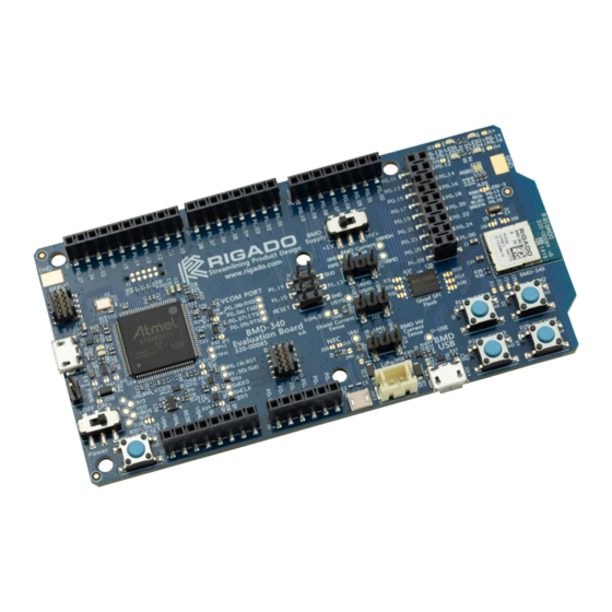
BMD-34x-EVAL User Guide Rev 2.0 Hardware Kit Figure 1 – BMD-34x-EVAL Board (Top View) BMD-340-EVAL: BMD-370-EVAL: • BMD-340 Evaluation Board • BMD-370 Evaluation Board • Micro-USB Cable • Micro-USB Cable • NFC antenna • NFC antenna BMD-341-EVAL: BMD-380-EVAL: • BMD-341 Evaluation Board •... -
Page 5: Development Tools
BMD-34x-EVAL User Guide Rev 2.0 Development Tools The tools listed below will aid in development with the BMD-34x Series Bluetooth modules. Not all tools will be required depending on which software suite is used. Tool Description Segger Embedded Studio Segger Embedded Studio is an easy-to-use integrated development environment with project management tools, editor and debugger supporting ARM Cortex devices. -
Page 6: Application Firmware Development
BMD-34x-EVAL User Guide Rev 2.0 Application Firmware Development This section walks through how to set up and program the BMD-340-EVAL Kit with an example application. 5.1 Set up the tool chain 1) Install Segger Embedded Studio request a license. 2) Download the latest nRF5 SDK. -
Page 7: Connect Bmd-34X-Eval To Computer
BMD-34x-EVAL User Guide Rev 2.0 5.2 Connect BMD-34x-EVAL to computer The evaluation board is provided with an on-board Segger J-Link programmer/debugger. 1. Connect the board to a computer using the USB cable provided. 2. The status LED, D5, will flash and then turn solid once the USB device is enumerated. 3. -
Page 8: Open An Example Project
BMD-34x-EVAL User Guide Rev 2.0 9. This confirms that the Eval board is properly recognized. 10. While still in the J-Link Commander session, save the Rigado-programmed public MAC address by typing in: savebin mac_addr.bin 0x10001080 8 11. Save the file to a convenient location for future use. -
Page 9: Hardware Description
BMD-34x-EVAL User Guide Rev 2.0 Hardware Description Design files for the BMD-34x-EVAL board may be found on the Rigado website. Figure 4 – Assembly Drawing (Top View) 6.1 Power The BMD-340-EVAL has five possible power sources: • USB from the debug interface •... -
Page 10: Usb Peripheral Power
The BMD-34x module has a configurable hardware reset. P0.18 is assumed to be used as the reset pin for all Rigado and Nordic example projects, and thus the evaluation board hardware is configured to use P0.18 as a reset. The Reset button can be configured to connect to an input on the interface IC or... -
Page 11: Figure 6 - Schematic - Reset
BMD-34x-EVAL User Guide Rev 2.0 The Reset button is connected to the IC used for the J-Link interface by default. Pressing reset while the interface IC is powered will caused a momentary reset signal on the nRESET output of the interface IC, which is connected via solder jumper to P0.18 of the BMD-34x module. -
Page 12: Buttons
BMD-34x-EVAL User Guide Rev 2.0 6.3 Buttons The Evaluation Board has four user buttons: User 1, User 2, User 3, and User 4. All buttons are active low; they will connect to ground when pressed. The button GPIO pins must be configured with internal pull-up resistors for proper operation when using the user buttons. -
Page 13: Virtual Com Port
BMD-34x-EVAL User Guide Rev 2.0 6.5 Virtual COM Port The evaluation board allows for easy serial communication with the BMD-34x Modules and a connected computer. The Interface IC provide a virtual COM USB device that connects to 4 GPIO pins on the module, allowing for UART communication with or without hardware flow control. -
Page 14: Nfc Connector
BMD-34x-EVAL User Guide Rev 2.0 6.7 NFC Connector Connection to an external NFC antenna is provided through a Molex flat-flex connector, Part number 051281-0594. Capacitors ‘C2’ and ‘C3’ provide tuning of the NFC antenna for resonance at 15.56MHz. Figure 10 – NFC Connector 6.8 Current Sensing Headers The evaluation board provides two current sensing headers. -
Page 15: External Segger J-Link™ Debug Interface
BMD-34x-EVAL User Guide Rev 2.0 6.9 External Segger J-Link™ Debug Interface External target hardware can be connected to J3 for firmware programming and debug. The Segger debug interface is implemented as shown in Figure 12. J3 is implemented with a 2x5 10-pin header on 0.05”... -
Page 16: Qspi
BMD-34x-EVAL User Guide Rev 2.0 6.10 QSPI A 64Mbit Quad SPI (MX25R6435F) flash is available on the BMD-34x-EVAL. This memory may be used for execute in place (XIP) directly from the flash as well as general data storage. Figure 13 – Quad SPI Flash 6.11 GPIO Jumpers There are many solder bridge jumpers on the board available to allow for configurability of the GPIO. -
Page 17: Header Pin-Out
BMD-34x-EVAL User Guide Rev 2.0 6.12 Header Pin-out Figure 15 – BMD-340-EVAL Board Pin-out Header J5 Header J7 Pin Name nRF52840 Function Pin Name nRF52840 Function VSHLD +3.3V Shield Power P1.08 P1.08 GPIO VSHLD +3.3V Shield Power P1.07 P1.07 GPIO RESET P0.18 nRESET / GPIO... -
Page 18: Related Documents
EXPRESSLY DISCLAIMS ANY EXPRESS OR IMPLIED WARRANTY OF FITNESS FOR USE IN HIGH-RISK ENVIRONMENTS. The customer using this product in a High-Risk Environment agrees to indemnify and defend Rigado from and against any claims and damages arising out of such use. -
Page 19: Environmental
Environmental 9.1 RoHS Rigado’s modules are in compliance with Directive 2011/65/EU, 2015/863/EU of the European Parliament and the Council on the restriction of the use of certain hazardous substances in electrical and electronic equipment. The declaration may be found here: https://go.rigado.com/RoHS-Modules... -
Page 20: Contact Information
List of Tables Table 1 – Useful Tools ..........................4 Table 2 – Rigado EVAL to Nordic DK cross reference .................. 7 Table 3 – Virtual COM Port ......................... 12 Table 4 – Header Pin-Outs ......................... 17 Table 5 – Document History ........................20 List of Figures Figure 1 –... -
Page 21: Document History
BMD-34x-EVAL User Guide Rev 2.0 Document History Revision Date Changes / Notes 2018-02-01 Initial release 2019-06-05 Added new modules and changed title to BMD-34x-EVAL User Guide Update Nordic SDK version Table 5 – Document History...
Need help?
Do you have a question about the BMD-34 EVAL Series and is the answer not in the manual?
Questions and answers