Table of Contents
Advertisement
Advertisement
Table of Contents

Related Manuals for Soehnle Professional 3035


Summary of Contents for Soehnle Professional 3035
- Page 1 Manual Terminal 3035 www.soehnle-professional.com...
-
Page 3: Table Of Contents
TABLE OF CONTENTS PAGE 1. GENERAL INFORMATION ......................6 1.1 Introduction ............................6 1.2 Intended use ............................6 1.3 Safety instructions ..........................7 1.4 Cleaning ............................... 7 1.5 Maintenance and service ........................7 1.6 Product Warranty/liability ........................8 1.7 Setup instructions..........................8 2. - Page 4 5.18.2 Defining a dynamic function key ....................61 5.18.3 Switching dynamic function keys on/off ..................63 5.18.4 Defining the level of the dynamic function keys ................. 64 5.18.5 Saving the settings of the dynamic function keys ..............64 5.18.6 Loading the settings of the dynamic function keys ..............64 5.18.7 Printing conditions ........................
- Page 5 6.7.10 Counting accuracy........................99 6.7.11 Display options with the Info key ..................101 6.7.12 Accepting current values into the fixed memory ..............101 6.7.13 Organizational data (identifier) ..................... 102 6.7.14 Settings in Setting Mode ....................... 102 6.8 Checking ............................106 6.8.1 Function keys ...........................
-
Page 6: General Information
3035 under Downloads. 1.2 Intended use The Soehnle Professional Terminal 3035 is a calibratable terminal for use in scales and weighing systems with commercially available DMS weighing and load cells. Up to three analogue measuring points (scales) can be simultaneously connected internally. Externally, a total of up to 29 measuring points are possible via CAN bus. -
Page 7: Safety Instructions
Never perform service work on the terminal while it is live. Improper installation will void the warranty. > The 3035 terminal must not be used in potentially explosive atmospheres. A special version is available for EX zones 2 and 22 >... -
Page 8: Product Warranty/Liability
1.6 Product Warranty/liability When a defect in the delivered item is attributable to Soehnle Industrial Solutions, Soehnle Industrial Solutions is entitled at its discretion to either remedy the defect or to supply a replacement. Replaced parts become the property of Soehnle Industrial Solutions. The statutory regulations apply if the defect remedy or replacement delivery fails. -
Page 9: Device Description
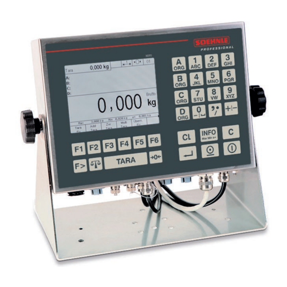
TFT 5.7" QVGA, dot matrix 320 x 240 pixels dimmable backlighting > Option: Soehnle Professional Micro-SD card (high-quality SLC memory card), memory capacity: Fixed memory for a total of 999 fixed values for all programs, alibi memory for 4 million entries and for software update >... -
Page 10: Symbols On The Display
2.3 Symbols on the display Symbols in the display toolbar Alibi memory use Alibi memory use Alibi memory use Keyboard lock Data logger empty Multirange 1 Multirange 2 Multirange 3 Resolution X10 Zero Hold function active Symbols in the information field of the display Exact target Below tolerance In tolerance... -
Page 11: Calibration Instructions
The scope of this notice is Germany. In other countries, conformity with national laws must be verified. The Terminal 3035 is approved for custody transfer class III and IIII within the EU. It complies with the type described in the type approval and the applicable requirements of Directives 2014/31/EU, 2014/30/EU, 2014/35/EU and EN 45501. -
Page 12: Switching On / Off
Switch on: Press the ON/OFF key. When switching on, the logo , terminal type 3035, filter type and the recognized measuring points are briefly displayed during the start routine. The scale is set to zero after the power-on process. When the machine is switched on, the last application program used is switched back on. -
Page 13: Operating Concept
3. OPERATING CONCEPT The operating concept is divided into two functional areas: Setting mode • Program mode • 3.1 Setting mode Here you make individual settings on the terminal to optimize the scale for your needs. Menu structure for setup mode: Setting mode Program settings Terminal... -
Page 14: Program Mode
3.2 Program mode Here you select the desired weighing application program. After selecting and calling the application program, the scale is ready to weigh. 3.3 Function keys The function keys F1 to F6 are available to call up the functions. These take on different functions depending on the program and situation. - Page 15 Info key, electronic type plate with calibration data, Calling up information on the application programs Function change key Scale change key Tare key Reset key / Delete tare Enter key Print key On / Off Display: The display shows different views depending on the situation. It is divided into the following display fields: SYMBOLLEISTE Aux.
-
Page 16: Setting Mode
4. SETTING MODE In the setting mode, program and weighing parameters are stored, which can be called up and individually set The adjustment is done by data input or selection from predefined parameters. The individual parameters are stored in logical groups within a multi-level family tree structure. Info: The modification options may be restricted in legal metrology. -
Page 17: Starting The Setting Mode
4.1 Starting the setting mode Switch on the terminal. After the switch-on routine, the terminal automatically starts the last activated application program. To call up the setting mode, switch to the setting functions level with the function change key. Function keys: Level Setting functions Secondary Prog... -
Page 18: Program Settings
Entries in setting mode: In most cases you make a selection from the various settings offered. For editable values, numeric or alphanumeric input is possible via the keyboard. Service area: The service area is secured by a password. The included parameters can only be maintained by trained service personnel. Please contact your Soehnle Industrial Solutions service centre. -
Page 19: Setting Mode Terminal Settings
> green > white > light blue > yellow > blue > magenta > red Factory setting: white Language Selection 1st language German (factory setting) 2nd language English or other languages can be adapted via the Soehnle Professional service program. - Page 20 Display Secondary display Selection > Second unit > tare value > x10 resolution > Gross/net > Current weight > reference quantity > reference weight > setpoint value > Difference to setpoint > Specific weight > Car registration number > Weight first/individual weighing >...
- Page 21 Date / Time Time Enter using the numeric keypad, the clock starts running Key Accept Date Input via numeric keypad Date format Selection European or imperial date Factory setting: European Numeric Keypad Entry in days [d]. Shelf life (days) Factory setting: 0 d Organizational data Designation ORG A Input...
- Page 22 Organizational data Fixed values Organizational Selection of existing fixed values from the database data A Scroll with the arrow keys F3 and F4. Call the desired fixed value with F6 Edit. Edit an existing fixed value from the database Press F6 to edit the marked fixed value. Parameter number is highlighted, call up via F6 Edit, input via numeric/alpha keyboard.
- Page 23 Error memory Error list Query the error list with position, date, time of the last error, number of errors, error number and description. Scroll back with arrow keys or F5. Protocol memory Query the list of the download log memory with position, date, time, code no. and description.
- Page 24 SD card data backup Import By pressing F6 Next, the current user settings are loaded from the micro SD card. The security question Import with YES or NO is displayed. No data will be loaded. Export By pressing F6 Next, the current user settings are saved on the micro SD card. Export for automatic import By pressing F6 Next the current user settings are saved on the micro SD card and in case of a software problem the setting parameters are automatically reloaded.
-
Page 25: Setting Mode Scale Settings
4.4 Setting mode Scale settings The first step is to select the scale (measuring point) with the scale change key, for which you want to configure settings. Only connected and active scales (measuring points) are displayed for selection. The settings and queries are made individually for each scale (measuring point). All setting and query options are identical for all scales (measuring points). - Page 26 Scales Parameters Switch-on zeroing Query off or on When on, the scale is set within the zero setting limit of the weighing range zero Selection only possible in the service area, subject to calibration. Autotara Selection off or on: No autotare on: Automatically tares the first weight value above the empty signal after stability on the scale Factory setting: off Tare summing...
- Page 27 Base point 4 Raw measured Query of the adjusted raw measured value from the 4 base point value The internal measuring point is on the central board of the terminal 3035 with the measuring point number internal measuring point Operating status...
-
Page 28: Setting Mode Communication Settings
4.5 Setting Mode Communication Settings In setting mode under Communication, you will find the following query or setting options Alibi memory Memory size Query Memory size 4.000.000 = 100% (display only with integrated and activated alibi memory) Fill level Query of the currently occupied fill level incl. - Page 29 Interface 1 RS232 (internal) Data bits Selection > 7 > 8 Factory setting: 8 Parity Selection > none > even > odd Factory setting: none Xon/Xoff Selection off or on Factory setting: off Factory setting Selection Do not execute: Individual settings on the interface are retained Execute: Resets interface to factory settings Interface Port 2 (For further details see also interface description 470.508.090)
- Page 30 Interface Port 2 Xon/Xoff Selection off or on Factory setting: off Factory setting Selection Do not execute: Individual settings on the interface are retained Execute: Resets interface to factory settings Interface Port 3 (For further details see also interface description 470.508.090) Use Interface Selection >...
- Page 31 (For further details see also interface description 470.508.090) Use USB Selection > none > 2795.14 > 2795.12+2795.20 > EDP > EDV 2 (unidirectional) > PC keyboard > Keyboard looping > Data logger If you are already using this function via another interface output, this selection position is shown as blocked.
- Page 32 Print image Query expression (OK) Selection on or off. If on, you will be asked after each printout whether the print was OK. If the answer is no, the print is repeated until OK is confirmed. Factory setting: off. Printout at G+T = 0 Selection on or off.
- Page 33 EDP settings EDP data set Selection for the format of the data record > EDP print image (variable) > EDV data record S20 > EDP data. 2790 as v2.10 > EDP data record Easylog Factory setting: EDP print image (variable) Selection EDP print image variable is the default setting according to the interface description 470.508.090 or can be freely configured via the service software.
- Page 34 0 to 4 using the numeric keypad Factory setting: 0 Code 1.scan (ORGA) Input Control commands from the interface description 3035 (document 470.508.090E) Factory setting: 0 Code 2.scan (ORGB) Input Control commands from the interface description 3035 (document 470.508.090E)
- Page 35 Barcode (for further details see chapter 7.10) Code 3.Scan (ORGC) Input Control commands from the interface description 3035 (document 470.508.090E) Factory setting: 0 Code 4.Scan (ORGD) Input Control commands from the interface description 3035 (document 470.508.090E) Factory setting: 0 Multiscan Timer Input of the time using the numeric keypad of the multiple scans for barcode capture;...
- Page 36 Batch processing (for further details see chapter 7.11) Batch code 1 Input Control commands from the interface description 3035 (document 470.508.090E) Factory setting: 0 Batch code 2 Input Control commands from the interface description 3035 (document 470.508.090E) Factory setting: 0...
- Page 37 Batch processing (for further details see chapter 7.11) Pause between batch code 1- Input Time for the pause between the batch codes, numerically via numeric keypad Factory setting: 100 ms Pause between batch code 2- Input Time for the pause between the batch codes, numerically via numeric keypad Factory setting: 100 ms Pause between batch code 3- Input...
- Page 38 IP address of the sensor Input IP address when the sensor is a server (host). Werkseinstellung: 010.010.005.005 IP port Input IP port Factory setting: 10001 3035 Socket type Selection > Client > Server Factory setting: Client Interface Mode Selection > read manually >...
-
Page 39: Setting Mode Settings Service
IP sensors (for further details see chapter 7.13) max. waiting time a. Data Input max. waiting time for data in milliseconds Factory setting: 4000 End of gen. Sensor data Selection > 0 > CR > LF > ETX Factory setting: 0 Ignore escape character '/ Selection >... -
Page 40: Basic Functions
5. BASIC FUNCTIONS 5.1 Switching on For a detailed description of how to switch on the terminal, refer to chapter 2.5 on page 13. 5.2 Switching off For a detailed description of how to switch off the terminal, refer to chapter 2.5 on page 13. 5.3 Program selection Selection among the available application programs. -
Page 41: Tare Function
Switching between several connected scales. Up to three analogue measuring points can be installed in the display unit 3035 or a total of up to 29 measuring points can be connected. In addition, a digital scale can be connected via the RS232 interface with the measuring point no. -
Page 42: Tenfold Display X10
5.8 Tenfold display x10 Shows the weight value with another decimal in 10 times higher resolution. Switch to the setting function level with the function change key. Aux. Prog- Setup Gross x 10 display mode Press the F2 x10 key. Approvable scales If the scale has been calibrated as verifiable, the tenfold higher resolution appears as long as the x10 key is held down. -
Page 43: Hold Function
5.9 Hold function In setting mode, a hold function can be activated separately for each connected measuring point (setting mode/scales/scale parameters/hold mode) The following hold functions are available: > Disabled: Hold is deactivated > Still/key: Hold at standstill outside empty signal, Cancel by pressing the on key >... -
Page 44: Secondary Display
5.10 Secondary display Shows supplemental information, such as second units, weight values when counting, differences from the setpoint, etc. Activating and deactivating the secondary display Switch to the setting function level with the function change key. Aux. Prog- Setup Gross x 10 display mode... - Page 45 When you call up the sub-menu Secondary display, a list of possible applications is displayed: You can move around in the list with the arrow keys F3 and F4 Functions of the secondary display The following function states can be set in the submenu Secondary display: >...
-
Page 46: Second Unit
5.10.1 Second unit The second unit is defined in the setting mode for each connected scale. The following second units are stored as standard: Adjusted unit Second unit The following units are available for individual set-up: Unit Abbreviation Conversion into g gram/kilogram g /kg 1 g /1,000 g... - Page 47 Use the arrow keys F3 and F4 to move to Second Unit in the list and select it by pressing F6 Next. You can move around the list with the arrow keys F3 and F4. With F6 "Enter", the second unit is defined. After selecting the second unit, press F1 End to return to the weighing mode.
-
Page 48: Organizational Data (Identifier)
Organizational data are used to assign identification features when documenting weighing operations, e.g. article number, address, customer, supplier, scale operator. They are available in all application programs. The 3035 display unit has 4 organization data memories. Each memory has >... - Page 49 Database for organizational data The use of the database for organizational data is only possible with an optional Soehnle Professional Micro- SD card. Contents that are called up frequently can be stored as fixed values in a database and called up as required.
- Page 50 For the requirement of a simple and multiple application for the maintenance of the Org-database for the designations and contents there is the PC - user software 3035. The user software is connected to the PC via the RS232, USB or Ethernet computer interface using the respective connection cable.
-
Page 51: Alphanumeric Input
5.12 Alphanumeric input The combined keypad can be used to make alphanumeric entries. As an option, the USB interface and the USB adapter cable for PC keyboard 2550.03.027 can be used to simplify input via a USB PC keyboard. Types of input fields Display fields without write capability Display/write fields with possibility of numerical input Display/write fields with possibility of alphanumeric input... -
Page 52: Key Lock
5.13 Key lock On the keyboard, you can lock individual, multiple or all keys. Locking the keys In setting mode, select Terminal / Keypad / Keypad lock. The keypad is shown schematically on the display. By pressing the key, you can now change the status of the key from open to locked and vice versa. -
Page 53: User Password
5.14 User Password Access to the setting mode and program selection can be blocked by assigning an individual password to prevent changes by unauthorised persons. In the setting mode, call up Terminal / User Password > Select Create/Change, in the input field that opens you can enter an alphanumeric password of up to 8 characters, then press F6 to accept it. - Page 54 F4 to select on and F6 to confirm. To use the password request function, the Login function setting must be enabled. Without the internal password system in the Terminal 3035, only an external computer password is requested, sent and released.
- Page 55 After switching on the terminal or calling up the login function with the Enter key, the Login window appears Press F5 Cancel to enter the menu Security question Login Cancel? Press F6 OK to display the password prompt Use the keypad to enter the required password and press the F6 key to accept it. The password with the command code is sent to the computer for checking and enabling and the hourglass appears on the display.
- Page 56 Create/change password (internal terminal password) For the internal password request function, the Login function and password request setting must be enabled. To call the setting mode, press F6 at key level Setting functions. Use the arrow key F4 to select Terminal, F6 Next. Use the arrow key F4 to mark the login function, F6 Next.
- Page 57 Use the keypad to enter the required password and press the F6 key to accept it. The entered password is checked: If the entry is correct, the EDP data record is sent with the registration confirmation, after which the terminal is in weighing mode.
-
Page 58: Sd Card Data Backup
5.16 SD card data backup On the optional Micro SD card (Alibi memory) it is possible to save the setting parameters in order to reset the data and functions at the terminal at a later date. Content for data backup All setting parameters (user) and the program selection of the terminal are saved. -
Page 59: Volume Measurement
3. 3-digit axis dimension from "001" to "999" in cm To accept the barcode in the terminal 3035, the terminating character at the end of the data string must be CRLF. The terminating character is provided by the scanner, the scanners are configured with the terminating character CRLF. - Page 60 Volume calculation Once the 3 axes have been accepted, the volume and volume weight are automatically calculated Displayed after volume calculation Volume Divisor Volume weight Data output There are various ways of triggering the transmission of data to a computer or printer. >...
-
Page 61: Dynamic Function Keys
5.18 Dynamic function keys The dynamic function keys enable the function keys F1 - F6 to be individually designed on a separate, programmable level. Here, process-dependent function keys can be configured and used. The dynamic function keys have the following characteristics: are configured via computer commands can be shown or hidden the function key level is freely selectable... - Page 62 Interpret A4 data as K-EDV command and execute it. Format: CCC:DDDDCCC Command-CodeDDDD Data Attention: If DDDD... is empty, the `:' must still be entered. Execute A6Data as EDP mode command Format: e = EDP mode A - H (must be written in capital letters) A7Set switching output X and display alternative text Format:...
-
Page 63: Switching Dynamic Function Keys On/Off
Action A4: F4 should be labeled "PRINT" and when pressed, trigger the print key of the 3035 terminal and send the corresponding data record / print image. <K530KF4;1L;DRUCK;A4;220:> Note: The corresponding control commands can be found in the interface description for the 3035 terminal with document number 470.508.090. -
Page 64: Defining The Level Of The Dynamic Function Keys
<K532KL2> 5.18.5 Saving the settings of the dynamic function keys Save dynamic function keys to the SD card via the 3035 terminal: Setting mode / Terminal / Dyn. function keys / Write file Save dynamic function keys to the SD card using external terminal software: Allows you to save the configurations on the SD card under the transferred name. -
Page 65: Printing Conditions
Load dynamic function keys from the SD card via external terminal software: This allows the configurations to be loaded from the SD card from the file with the transferred name. Format: <KcccKfff> where: ccc3-digit command code 533 fffFILENAME .TXT (see above) Example: <K533KTEST.TXT>... -
Page 66: Application Programs
6 APPLICATION PROGRAMS The various application programs of the Soehnle terminal 3035 offer you comprehensive solutions for your weighing tasks. You can customize the application programs in the setting mode to meet your specific needs. For details, refer to the respective chapter Settings in Setting Mode. -
Page 67: Navigation In The Application Programs
Use the arrow keys F3 up and F4 down to mark the user program, then press F6 to accept it. 6.3 Navigation in the application programs The function keys F1 to F6 are available to control the functions. These take on different functions depending on the program and situation. The respective function is shown on the display in the function bar. -
Page 68: Weighing And Taring
6.5 Weighing and taring Basic function weighing, determination of gross and net weights Info: The following description of the tare functions applies to the factory setting of the options > Autotara in position off > Tare summing to position off, i.e. new tare overwrites old tare Selecting options in the scale setting mode menu 6.5.1 Function keys The function keys F1 to F6 are available to control the functions. -
Page 69: Display Information Field
Tip: To display the tare weight or a second unit, for example, you can press the F3 key to open an additional secondary display. The setting which value is to be shown in the secondary display is made in setting mode under Setting mode / Terminal / Display / Secondary display. -
Page 70: Weighing Without Taring
6.5.4 Weighing without taring Place the weighing piece on the scale, the weight is displayed with the note Gross. 6.5.5 Manual taring Determination and taring of an unknown container weight. Place the empty container on the scale. Press the key The tare value is saved, the weight display goes to zero and the weight is displayed with the message Net. -
Page 71: Multiplicative Tare
6.5.7 Multiplicative tare Determining the tare of several containers of equal weight with known tare weight. Press the F4 Multi Tare key in the Tare functions level. Place a container on the scale or enter the known tare weight via the numeric keypad. Confirm with F6 Accept. -
Page 72: Intermediate Tare
6.5.9 Intermediate tare Unknown tare values are added to the existing tare memory, the net value remains unchanged. Press the F3 Zw Tara key in Tare functions level. Put on the additional tare weight. Confirm with F6 Accept. The additional tare weight was stored in the tare memory, the net value remains unchanged. Repeat the procedure for further additional tare. -
Page 73: Fixed Tare Value Memory
6.5.11 Fixed tare value memory The use of the fixed tare memory is only possible with an optional Soehnle Professional Micro-SD card. Known tare weights can be stored in a power-failure-proof memory and called up as required. You can store 999 reference weights in a fail-safe memory. -
Page 74: Error Messages When Taring
b) Call up the list of fixed tare values for taring: In the Tare functions level, press the F1 Tare Fix key. The display shows the last fixed tare value called up. Selection within the list Scroll with the arrow keys. Call the desired fixed value with F6 Accept. -
Page 75: Accepting Current Values Into The Fixed Memory
6.5.14 Accepting current values into the fixed memory For direct transfer of fixed tare values into the fixed memory, first transfer the tare value or enter tare hand. Gross Press the F5 key to confirm. Fix, the value can be stored directly in the fixed memory. The input window for the fixed tare values appears. -
Page 76: Settings In Setting Mode
6.5.16 Settings in Setting Mode With the parameters in the setting mode you can adapt the weighing and taring application program to your individual requirements. To call up the setting mode, press key F6 Setting mode in the Setting functions level and call up the program settings with F6 Accept. -
Page 77: Totalizing And Picking
Weighing and taring Display information field Select which data should be displayed in the information field > Factory setting: Switch between the individual functions used, e.g. switching functions inputs and outputs and organization data memory. > IO control: Continuous display of output and input states >... -
Page 78: Display View
2. Tare functions level: Tare Int. Multi Save Tare Tare Tare 3. Setup functions level: Aux. Prog- Setup Gross display Mode 6.6.2 Display view After the first totalizing operation, the display changes from the basic view to the totalizing view, provided that the setting Display information field is set to factory setting. -
Page 79: Display Information Field
Illustration of display secondary display with x10 display Gross 6.6.3 Display information field In the setting mode / program settings / buzzer + Comm. / Display information field, you can set which data is displayed in the information field. The following options are available: >... -
Page 80: Tare Function
6.6.4 Tare function The description and detailed instructions for the tare function can be found in chapter 6.5. 6.6.5 Operating the totalizing function Use the function change key to call up the totalizing functions level Plus F6 By pressing the F6 Plus key, the weight on the weighbridge is transferred to the totalizing memory. The transaction counter and the consecutive number are increased by 1. -
Page 81: Options For Displaying Totals
6.6.6 Options for displaying totals Clearing the totalizing memory The following functions can be assigned to the Total function key in Setting mode: > Display, print and delete totalsAfter pressing the Total function key, the totals are displayed for 3 seconds, the contents of the memory are printed and deleted at the same time. -
Page 82: Assigning And Deleting The Sequence Number
6.6.10 Assigning and deleting the sequence number Each entry (plus, hand, cancellation) in the totalizing memory is assigned a four-digit consecutive number. The sequence number is not reset in the factory setting. Optionally, you can specify in setting mode to reset the sequence number: >... -
Page 83: Displaying Individual Items
Info: Display information field with current totals In the setting mode / program settings / buzzer + Comm. / Display information field, the total can be set, then the total is always displayed in the information field. 6.6.14 Displaying individual items Within a summation, you can call up the individual items from the totalizing memory by Press the and the F5 Plus key in succession. -
Page 84: Display Options With The Info Key
6.6.15 Display options with the Info key Pressing the key gives you the following choice: > F1 Tare FixDisplay of the stored tare fixed values (tare fix memory). > F4 Total Display of the current totals in the totalizing memory >... -
Page 85: Organizational Data (Identifier)
Press the F5 key to confirm. Fix, the value can be stored directly in the fixed memory. The input window for the fixed tare values appears. To enter the designation of the fixed tare value, press the F6 key Edit. Enter the designation with the keypad and confirm the entry by pressing the F6 key. - Page 86 Totalizing and picking Auto totalisation/commiss. Selection from or on On means that only the first position must be stored by pressing the Plus key, all other positions are automatically stored in the totalizing memory according to weight and stability. Factory setting: off running time No.
-
Page 87: Counting
6.7 Counting Counting of parts of equal weight. The weight of the individual parts (reference weight) is determined from a known small quantity of counted parts. This is then used as a divisor to determine the number of pieces from the weight of an unknown quantity of these counting parts. -
Page 88: Display View Counting
6.7.2 Display view Counting Reference weight Gross Gross Tip: For an additional display, e.g. of the reference quantity, the x10 resolution or the tare weight, you can press the F3 key to open an additional secondary display. The setting which value is to be shown in the additional display is made in the setting mode under Setting mode / Terminal / Display / Additional display. -
Page 89: Display Information Field
6.7.3 Display information field In the setting mode / program settings / counting / display information field, you can set which data are displayed in the information field. The following options are available: > Counting: Toggling between the individual functions used, counting with the reference weight and weight value in gross / net e.g. -
Page 90: Counting Function
6.7.5 Counting function The determination of the reference weight is possible via the following function keys: > Function key F1 Ref 10Reference weight determination from a pre-set reference sample quantity. Place 10 counting pieces on the scale, then press the F1 Ref 10 key The scale determines the reference weight and displays "10 pieces". - Page 91 a) Calling up the Ref Fix memory to process the counting articles: Press key and then F2 Ref Fix Selection of existing fixed values from the list Scroll with the arrow keys F3 or F4 until the desired memory location is reached, accept the desired fixed value with F6 Edit.
-
Page 92: Totalizing And Picking
When the fixed value is called up, target piece counts, tolerances for piece control and tare value are also taken over, if saved. Delete all stored reference weights using the "Delete reference weights" function in setting mode Note If the fixed memory recall via barcode function is activated and a fixed value not contained in the fixed memory is recalled, the error message "Error 83 - Fixed value not available"... - Page 93 Display view After the first totalisation, the display changes from the basic Count view to the Totalizing view if the setting "Display information field" is set to Count. Operation of the totalizing functions Call the totalizing functions level with the function change key >...
- Page 94 Selection options for displaying the total Clearing the totalizing memory The following functions can be assigned to the Total function key in Setting mode: > Display, print and delete totalsAfter pressing the Total function key, the totals are displayed for 3 seconds, the contents of the memory are printed and deleted at the same time.
- Page 95 Item counter The transaction counter only counts the transactions that have actually been totalled. For each new operation with plus, manual or automatic totalizing, the item counter is incremented by 1. The transaction counter runs up to 999, after which an error message is displayed. If the transaction is cancelled, the transaction counter is reduced by 1.
-
Page 96: Reference Statistics
Display individual items Within a totalizing function, you can call up the individual items from the totalizing memory by pressing - and the plus key F5 in succession. The item list starts with the most recent entry. Cycle through the list with the arrow keys F3 (older entries) and F4 (newer entries). The last 50 entries can be called up. -
Page 97: Piece Control
Example of reference statistics display: Samples Lightest part 24,448 g Heaviest part 24,750 g Deviation 0,302 g Mean value 24,589 g Printout of the statistics Press the function key F1 "Print". Print output is only possible by using the interface on printer 1 "2795.14". If necessary, the print image with the required print output must be adapted via the service program. -
Page 98: Counting With Several Weighbridges
Switching points for piece control If you want to transmit the control values via the interface, e.g. to a control traffic light or a controller, an I/O card must be installed in the terminal. This must be activated in the setting mode under Program settings / Counting / IO Pre-assignment must be activated with Execute. -
Page 99: Counting Accuracy
6.7.10 Counting accuracy In the setting mode you can influence the counting accuracy of your scale in the program settings / counting. > Standard reference quantity The reference quantity 10 is set at the factory. You can set this number between 1 and 99. For small parts, it is advisable to use a larger number of parts to determine the reference weight. - Page 100 No more parts may be placed on the scale than are already on the scale. Reason: A reference weight calculation may only be carried out if the quantity on the scale is exactly correct. It would not make sense to calculate the reference weight from 10 parts, add 1,000 parts and then carry out the optimisation with 1,010 parts.
-
Page 101: Display Options With The Info Key
6.7.11 Display options with the Info key Pressing the key gives you the following options: > F1 Tare Fix Display of the stored tare fixed values (tare fix memory). > F2 Ref Fix Displays the stored reference weights (Ref-Fix memory) >... -
Page 102: Organizational Data (Identifier)
The designation of the reference weight is entered by pressing the F6 key "Edit". Enter the designation with the keypad and confirm the entry by pressing the F6 key "Accept". The article number is entered in the same way. 6.7.13 Organizational data (identifier) Detailed information on the organizational data can be found in chapter 5.11. - Page 103 weight The scale optimises the reference weight when additional parts are placed on the scale. The upper limit of the optimisation will be entered in percent of the weighing range. Example: 50% of the weighing range 60 kg, optimisation takes place up to 30 kg. Example: 0%, optimisation switched off.
- Page 104 weight and stability. Factory setting: off running time No. Reset Selection under which condition the consecutive number of the totalisation / picking is to be reset > not active > Clear total memory > Switch off > Function key (activates a separate function key) Factory setting: not active Counting Sum key function...
- Page 105 (Cancel without accepting the input with F5 Cancel.) Other parameters are processed in the same way. Exit the list of fixed values Press the F5 Back key to exit the list. Fixed value Call Selection whether the fixed value is called up via memory location number or article number.
-
Page 106: Checking
6.8 Checking Checking is checking whether the sample corresponds to a target weight within a specified tolerance range. This function can also be used for weighing to a specified setpoint with a lower and upper tolerance limit. Tolerance deviations from the target value can be determined in the adjusted unit or in %. In the program settings for control, the setpoint comparison with the current measured value (factory setting) or totalizing memory can be selected. -
Page 107: Display View
6.8.2 Display view Gross Check Total Clear Plus point Tip: For an additional display of, for example, the setpoint or the difference to the setpoint, you can press the F3 key to open an additional secondary display. The setting which value is to be shown in the secondary display is made in the setting mode under Setting mode / Terminal / Display / Secondary display. -
Page 108: Display Information Field
6.8.3 Display information field In the setting mode / program settings / check / display information field, you can set which data are displayed in the information field. The following options are available: > Factory setting: Change between the individual functions used, e.g. control light, totalizing memory, organization data memory. - Page 109 Control status Traffic light colour Special characters Below tolerance limit Yellow Within tolerance Green Setpoint reached exactly Green Above tolerance limit In the secondary display with the Control light setting, no symbols are displayed but only the colours in the display field of the secondary display.
- Page 110 Edit an existing fixed value from the list Edit the selected fixed value with F6 Edit. Parameter name is highlighted, call up with F6 Edit, input via keyboard. Accept the input with F6 (Cancel without accepting the input with F5 Cancel). Other parameters are edited in the same way.
-
Page 111: Totalizing And Picking
Switching points during control If you want to transmit the control values via the interface, e.g. to a control traffic light or to a controller, an I/O card must be installed in the device. This I/O card must be activated in setting mode under Program settings / Control / IO preassignment with Execute. - Page 112 Operation of the totalizing functions Use the function change key to call up the totalizing functions level Plus F6 By pressing the F6 Plus key, the weight on the weighbridge is transferred to the totalizing memory. The transaction counter and the consecutive number are increased by 1. Before totalizing again, the scale must be unloaded at least up to the unload factor defined in the setting mode.
- Page 113 Relief factor for summation (Parameter is not used in the picking function) In setting mode, you can specify that the scale must be unloaded by a certain number of digits between the time you place each item on the scale in the totalizing function. If the scale is not unloaded, the weight value is not saved in the totalizing memory and is displayed with the error message Error 55 Place weight on scale.
- Page 114 Display Current totals view: Info: Display information field with current totals In setting mode / program settings / check / display information field, the total can be set, then the total is always displayed in the information field. Display individual items Within a totalizing function, you can call up the individual items from the totalizing memory by pressing and the F5 Plus key in succession.
-
Page 115: Display Options With The Info Key
Summation of control items out of tolerance The accumulation of control items that lie outside a specified tolerance range can be prevented. If the weight value is outside the tolerance, the error message Error 27 "Out of tolerance" is displayed after pressing the F6 Plus key. -
Page 116: Organizational Data (Identifier)
The input window for the setpoint value appears. The designation of the setpoint is entered by pressing the F6 Edit key. Enter the designation with the keyboard and confirm your entry by pressing the F6 key. The article number is entered in the same way. 6.8.9 Organizational data (identifier) Detailed information on the organizational data can be found in chapter 5.11. - Page 117 Check Summation out of tolerance Selection inside or outside Here it is defined whether summations into the totalizing memory may only be made for values within the tolerance or also for values outside the tolerance. Factory setting: Outside Totalizing or picking Select Totalize or Pick for the following settings.
- Page 118 Check Check fixed values Editing fixed values Check Selection of existing fixed values from the list Scroll with the arrow keys F3 and F4. Call the desired fixed value with F6 Edit. Edit an existing fixed value from the list Press F6 to edit the marked fixed value.
- Page 119 Check Display information field Select which data should be displayed in the information field > Factory setting: Change between the individual functions used, e.g. control light, totalizing memory, organization data memory. > Control display: Continuous display of the traffic light function. >...
-
Page 120: Error Messages
7. Error messages Error message Cause /Aid / Info Scale unsuitable for part weight, if necessary change the 4 REF Weight too small setting in the setting mode 5 zeroing not possible Deviation from zero point too large Empty scale, scale in under- or overload, tare hand input with 6 Taring not possible tare value over maximum load Selected function does not allow to print, change or extend... -
Page 121: Further Information
> Communication (alibi memory, interfaces, print image, barcode, IO-control) > Printing > Service (error messages, software update) > and many more please refer to the handbook 3035 (document no. 470.051.168) under: https://www.soehnle-professional.com/en/site/documents Please visit the customer center of our website www.soehnle-professional.com and select... - Page 124 Soehnle Industrial Solutions GmbH Gaildorfer Straße 6 DE-71522 Backnang Phone: +49 71 91 / 34 53 - 220 Fax: +49 71 91 / 34 53 – 211 info@sis.gmbh www.soehnle-professional.com 470.051.172EN V1.5 03/21 Subject to technical changes.
Need help?
Do you have a question about the 3035 and is the answer not in the manual?
Questions and answers