Table of Contents
Advertisement
Right choice for ultimate yield
LSIS strives to maximize customers' profit in gratitude of choosing us for your partner.
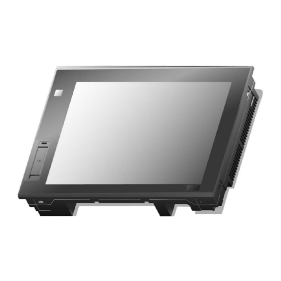
Human Machine Interface
iXP Series
Read this manual carefully before
installing, wiring, operating, servicing
or inspecting this equipment.
Keep this manual within easy reach
for quick reference.
XGT Panel
User's Manual
iXP50-TTA
iXP70-TTA
iXP80-TTA
iXP90-TTA
http://www.lsis.com
Advertisement
Table of Contents

Subscribe to Our Youtube Channel
Related Manuals for LSIS iXP Series


Summary of Contents for LSIS iXP Series
- Page 1 Right choice for ultimate yield LSIS strives to maximize customers' profit in gratitude of choosing us for your partner. Human Machine Interface XGT Panel iXP Series User’s Manual iXP50-TTA iXP70-TTA iXP80-TTA iXP90-TTA Read this manual carefully before installing, wiring, operating, servicing or inspecting this equipment.
- Page 2 Safety Precautions Before using the product… To use the product safely and effectively, please read this instruction manual thoroughly before use. ► Please keep to the safety precaution, for it is to prevent accidents and potential danger from occurring. ► Safety precaution is classified into ‘Warning’ and ‘Caution’ and their meanings are as follows. Warning Violating the instruction may result in serious personal injury or death.
- Page 3 Safety Precautions Design Precautions Warning Install a safety circuit external to the HMI to protect the whole control system in case of external power supply trouble. Serious trouble may occur to the entire system due to erroneous output/operation of the HMI. Design Precautions Caution In/output signal or communication cable should be at least 100mm apart from...
- Page 4 Safety Precautions Wiring Precautions Warning Be sure to turn off the HMI and external power before wiring. Otherwise, it may result in an electric shock or damage to the product. Caution Wire correctly by checking each of the product’s rated voltage and terminal layout. Otherwise, it may result in fire, electric shock or erroneous operation.
- Page 5 Safety Precautions Startup and Maintenance Precautions Warning Do not touch the terminals while power is on. Otherwise, it may cause electric shock or erroneous operation. Turn off the HMI and external power when cleaning or tightening the terminal. Otherwise, it may cause electric shock or erroneous operation.
- Page 6 1.2, 2, 3.2, 4.4, 5, 7 9, Appendix 1 3. Multimedia function is removed 1, 2, 4 ※ The number of User’s manual is indicated the right side of the back cover. ⓒ LSIS Co., Ltd 2013 All Rights Reserved.
-
Page 7: Table Of Contents
Contents Chapter. 1 General Introduction ..................1-1~1-8 1.1 How to use the Instruction Manual ..........................1-1 1.2 Feature ..................................1-3 1.3 Terminology ................................... 1-8 Chapter. 2 System Configuration ................... 2-1~2-11 2.1 Part Names ................................... 2-1 2.2 System Configuration ..............................2-6 Chapter. - Page 8 Contents Chapter. 6 Viewing Information of PLC Connection Status ........6-1~6-8 6.1 PLC Communication Configuration Settings ......................6-2 6.2 Connection Information ..............................6-3 6.3 PLC Information ................................6-4 6.4 History of PLC Error ..............................6-4 6.5 History of PLC Mode Conversion ..........................6-5 6.6 History of PLC Power ..............................
- Page 9 Contents 10.2 Wiring ..................................10-5 10.2.1 Power wiring ..............................10-5 10.2.2 Ground wiring ..............................10-8 Chapter. 11 Maintenance ..................... 11-1~11-3 11.1 Maintenance................................11-1 11.2 Daily Maintenance ..............................11-1 11.3 Periodical Maintenance ............................. 11-2 Chapter. 12 EMC Standard Certification ..............12-1~12-2 12.1 Requirement for EMC Standard Certification ......................
-
Page 10: Chapter. 1 General Introduction
Chapter 1. General Introduction 1.1 How to use the Instruction Manual This instruction manual provides information such as specification, how to use, etc. of the product needed to operate iXP series of XGT Panel. iXP series is characterized as follow;... - Page 11 Chapter 1. General Introduction The user manual’s configuration is as follows. Sequence Category Contents It describes this manual’s configuration, product’s feature and term. Chapter 1 General Introduction Chapter 2 System Configuration It describes feature and system configuration of each XGT Panel. It describes XGT Panel’s general and function specification.
-
Page 12: Feature
Chapter 1. General Introduction 1.2 Feature iXP series has the following features. Various types of external interface (a) Supporting various storage media of USB and SD card, it maximizes the customer’s usability. Multimedia type provides interfaces of video input, audio input, video output, and audio output so as to add the functions needed to exert high performance. - Page 13 Chapter 1. General Introduction (b) Presence sensor is placed at the front upper side so as to control backlight power source as it detects the presence. This enables the user to turn on/off backlight either by touch or as it detects a movement of human body or not, and thereby contribute to energy saving.
- Page 14 Chapter 1. General Introduction (c) Various communication connectors are placed at the lower side so that it can be connected in a variety of types with the control device such as PLC, inverter, etc. With two channels of USB HOST attached, it provides total 3 USB Hosts including one channel at front side.
- Page 15 Chapter 1. General Introduction (b) It provides the transmission function from USB storage device. Data change High quality screen (a) It provides the high quality screen and clearness by high quality LCD. It adopts TFT LCD which supports the 24-bit Color. (b) It provides diverse graphic type.
- Page 16 Chapter 1. General Introduction Multilingual and diverse font (a) It supports the multilingual function. It transmits the Windows/User font used in computer to XGT Panel. Additional language development is not necessary. Multilingual language is an advantage of Windows CE. (b) It can express four kinds of language simultaneously.
-
Page 17: Terminology
Chapter 1. General Introduction (h) Providing video input function (Multimedia type only) Analog camera allowing input of signals such as NTSC, PAL, SECAM, etc. can be connected using coaxial cable. It provides preview function that allows watching video input data, and record/play functions as well. ... -
Page 18: Chapter 2 System Configuration
Chapter 2 System Configuration Chapter 2 System Configuration Characteristic of each iXP series and its system configuration are as follow; 2.1 Part Names 2.1.1. iXP50 -TTA /DC ○ ○ ○ ○ ○ ○ ○ ○ ○ ○ ○ ○ ○... -
Page 19: System Configuration
Chapter 2 System Configuration Name Description ○ Power status LED Indicating the state of device (On: Green) 1) Logging/Recipe/Screen Data Backup ○ USB Device 2) Send project data and XP-Run time 3) Receive back data and project file Composed of three ports (Front side 1 port, Lower end 2 ports) ○... - Page 20 Chapter 2 System Configuration 2.1.2. iXP70 (80/90)-TTA /AC (DC) ○ ○ ○ ○ ○ ○ ○ ○ ○ ○ ○ ○ ○ ○ ○ ○ ○ ○ ○...
- Page 21 Chapter 2 System Configuration Name Description ○ PIR sensor Sensor that detects human movement 1) Analog Touch Panel: Input by user’s touch ○ Front Part 2) LCD: Screen indication ○ Power status LED Indicating the state of device (On: Green) 1) Logging/Recipe/Screen Data Backup ○...
- Page 22 Chapter 2 System Configuration When you unpack the produce box to use XGT Panel, you can find prevention switch mounting on the device setting switch that prevents battery discharge. Device setting switch consists of 6 switches. Of them, 3rd switch has battery discharge preventing function.
- Page 23 In order to use XGT Panel, it is necessary for XP-Builder to prepare project data and transmit it to XGT Panel. Normally you can connect with XGT Panel using USB 2.0 Device. Maximum Communication speed is 480Mbps. iXP Series USB Cable USB Device USB Host 2.0...
- Page 24 Chapter 2 System Configuration 1:1 connection will be supported just in case LAN environment is not built. Ethernet Cross Cable 10Base-T/100Base-TX 10Base-T/100Base-TX...
- Page 25 If it is impossible to transfer project data using Communication, you can use USB storage device and SD memory Card. For more information, please look at the Chapter 7 and XP-Builder User’s Manual. iXP Series Used for saving update file and...
- Page 26 Chapter 2 System Configuration With RS-232C wireless converter in use, it enables communication between XGT Panel and control device iXP Series RS-232C RS-232C RS-232C RS-232C Wireless converter Wireless converter Wireless converter Wireless converter With RS-422/485 cable in use, it enables connections such as 1:1, 1: N, N: 1 and N: M up to 500m.
- Page 27 Chapter 2 System Configuration With N: 1 and N: M in connection, it enables connection in a RS-485 method. iXP Series RS-485 RS-485 cable (Max. 500m) RS-485 iXP Series RS-485 RS-485 RS-485 cable (Max. 500m) It enables communication configuration using LAN through Ethernet switch hub and communication configuration using a direct cable.
- Page 28 Chapter 2 System Configuration With LAN in use, it enables to connect multiple numbers of XGT Panels with the control device. It also enables remote control from PC and operation through a data server. iXP Series iXP Series Ethernet hub Note (1) For how to make Ethernet cable, please see the Communication User’s Manual.
-
Page 29: Chapter. 3 Standard Specification
Chapter 3. Standard Specification Chapter 3. Standard Specification 3.1 General Standards iXP Series general standard is as follows. Category Standard Related standard Ambient operating 0℃∼+50℃ temperature Storage -20℃∼+60℃ temperature Operating 10∼85%RH, non-condensing. humidity Storage 10∼85%RH, non-condensing. humidity Occasional vibration count... -
Page 30: Function Standards
: As an index representing the pollution degree of an environment to determine the insulation of a device, pollution degree 2 generally means the status generating non-conductive contamination. However, it also contains the status generating temporarily conduction due to condensation. 3.2 Function Standards iXP Series function standard is as follows. (1) DC type Item iXP50-TTA/DC... - Page 31 Chapter 3. Standard Specification Item iXP50-TTA/DC iXP70-TTA/DC iXP80-TTA/DC iXP90-TTA/DC SD Card 1 Slot (SDHC) Detection range: side 1-1.5m, front 40-50cm Human sensor Angle: high/low 100°, left/right 140° (detecting 5-20 micron infrared light) Audio output LINE-OUT 1 channel Expansion module For communication and I/O option module (available later) VM module 4 channels video input (available later) Multi-language...
- Page 32 Chapter 3. Standard Specification (2) AC type Item iXP70-TTA/AC iXP80-TTA/AC iXP90-TTA/AC Display type TFT LCD 30.7cm (12.1”) 38.1cm (15”) Screen size 26.4cm (10.4”) Display Resolution 800 x 600 pixel (SVGA) 800 x 600 pixel (SVGA) 1,024 x 768 pixel (XGA) Color indication 16-bit and 24-bit Color (default: 16-bit Color) Left/Right: 80 deg.
- Page 33 Chapter 3. Standard Specification Item iXP70-TTA/AC iXP80-TTA/AC iXP90-TTA/AC Protection standard IP65 Dimension (mm) 270.5 x 212.5 x 60.0 313.0 x 239.0 x 56.0 395.0 x 294.0 x 60.0 Panel cut (mm) 259.0 x 201.0 301.5 x 227.5 383.5 x 282.5 Rated voltage AC 100-240V Power consumption (W)
-
Page 34: Chapter. 4 System Configuration
Chapter 4. System Configuration Chapter 4. System Configuration It describes the system configuration including XGT Panel’s time setting, Ethernet connection setting, and connection with PC and backlight. If you press [Settings] button in XGT Panel’s basic screen, you can set XGT Panel’s environment as follows. Main screen System Configuration screen... -
Page 35: Touch Calibration
Chapter 4. System Configuration 4.1 Touch Calibration When the location is not recognized in XGT Panel, Touch’s scale can be adjusted in XGT Panel. If you press [Touch Calibration] button in System Configuration, the setting screen shows up. If you press five ‘+’ marks, XGT Panel’s touch location adjustment is completed. -
Page 36: Backlight Setting
Chapter 4. System Configuration 4.2 Backlight Setting If you press [Backlight Setting] button in [System Configuration] screen as follows, setting screen shows up. [Dialog box explanation] Name Explanation Brightness It may adjust brightness of backlight. It doesn’t turn off backlight power. Do not turn off backlight Turn off backlight after idle time It automatically turns off backlight if not in touch for a certain period of time. -
Page 37: Pir Sensor
Chapter 4. System Configuration 4.2.1 PIR sensor The XGT Panel’s backlight is activated by detecting movement around the XGT Panel. If you approach the XGT Panel when the display is off, movement around the XGT Panel from the left, right or front, is detected and turns on the backlight. (1) The XGT Panel has a detection range of 1-1.5m from both sides. -
Page 38: Date Time Setting
Chapter 4. System Configuration 4.3 Date Time Setting If you press [DateTime Setting] button in [System Configuration] as follows, you can set XGT Panel’s data and time. Remark You can set data/time at device information of communication dialog at the XP-Builder. For details, please refer to the XP-Builder’s manual. -
Page 39: Ethernet Setting
Chapter 4. System Configuration 4.4 Ethernet Setting If you press [Ethernet Setting] button in [System Configuration] screen as follows, you can change IP to use Ethernet. You can change IP address by pressing [Set] button of each IP address, Subnet Mask and Gateway. By pressing OK button, changed IP information is reserved. -
Page 40: Environment Setting
Chapter 4. System Configuration 4.5 Environment Setting If you press [Environment Setting] button in [System Configuration] screen as follows, you can set ‘Auto Goto Screen’ and ‘Buzzer On/Off’. - Page 41 Chapter 4. System Configuration Name Explanation Goto screen after boot up When setting [Auto Goto Screen], XGT Panel is rebooted. Or when downloading the edit data is completed, the screen automatically shows up. If you cancel this setting, the user should press ‘Start’ button in order to move to the screen. Quick Start When starting screen, screen shows promptly without showing progress bar because it doesn’t caching the image in advance.
- Page 42 Chapter 4. System Configuration Set Background Image If you select the image through [Set Background Image], background image of waiting screen is set as the selected image. If you want to cancel, press [Delete Background Image] [Background Image Selection Screen] [Use boot image] With an option selected, you cannot use it unless it is the image of different resolution from that of XGT Panel or 32-bit image.
- Page 43 Chapter 4. System Configuration Printer Settings If there are no information of printer, the pop-up will be shown. If the pop-up is shown, you need to set up the printer to use XP-Builder 4-10...
- Page 44 Chapter 4. System Configuration Printer Settings Name Explanation (대화상자) Port Set up the printer port. Printer type Set up the printer type. Print direction Set up the print direction - width or height Set up the print color – color or mono Print color High quality print Set up the printer quality...
-
Page 45: Sound Setting
Chapter 4. System Configuration 4.6 Sound Setting It may adjust XGT Panel sound volume. [Sound Setting Screen] [Dialog box Explanation] Name Explanation Sound volume It may adjust sound output volume. Input source It designates the sound input type in Line-in or microphone. This function is supported in multimedia type XGT Panel only. -
Page 46: Xp-Remote Setting
Chapter 4. System Configuration 4.7 XP-Remote Setting Settings of XP-Remote that can remotely adjust XGT Panel can be changed. [XP-Remote Setting Screen] [Explanation of dialog box] Name Explanation Allow XP-Remote to connect It allows connecting remote XP-Remote. Max. of XP-Remote connections It designates the maximum number of XP-Remote connected with XGT Panel. -
Page 47: Buzzer Setting
Chapter 4. System Configuration 4.8 Buzzer Setting It may adjust volume and height of XGT Panel Buzzer. [Buzzer Settings Screen] [Explanation of dialog box] Name Explanation Buzzer On/Off It may turn on or off the buzzer that occurs when in touch mode Buzzer volume It may adjust the volume of Buzzer Buzzer tone... -
Page 48: Chapter. 5 Diagnostics
Chapter 5. Diagnostics Chapter 5. Diagnostics It describes the diagnosis function for XGT Panel’s communication terminal, screen and touch function. If you press [Diagnostics] button on the XGT Panel’s basic screen, the menu for diagnosis shows up. Main Screen Environment setting screen... -
Page 49: Screen Diagnosis
Chapter 5. Diagnostics 5.1 Screen Diagnosis If you press [Screen] button, screens continuously change into diverse color with buzzer. For XP30-BTA/DC product, screen changes into 8 steps’ light. After all screen for diagnosis pass. Then, Close button shows up with white ground. If you press Close button, the initial screen shows up. -
Page 50: Touch Diagnosis
Chapter 5. Diagnostics 5.2 Touch Diagnosis If you touch the screen, the touched location is displayed as follows. If pressing the [OK] button, you can quit the screen. Touch diagnosis If the touched location is not correct, reset the Touch setting. For detailed information, please refer to the Chapter 4. -
Page 51: Backup Memory Diagnosis
Chapter 5. Diagnostics 5.3 Backup Memory Diagnosis If you press [Backup Memory] button, you can see the result of diagnosis in the result windows. Completion of Backup Memory diagnosis Remark (1) If ‘NVRAM Data Access … Fail’ error is occurred, please contact with customer service center. (2) If ‘BATTERY STATUS …... -
Page 52: Flash Memory Diagnosis Function
Chapter 5. Diagnostics 5.4 Flash Memory Diagnosis Function If you press [NOR Flash] button, you can see the result of diagnosis in the result widows. Completion of Flash Memory diagnosis Remark If ‘Read Disk Information Error!’ occurs, please contact with Customer service center. -
Page 53: Serial Communication Diagnosis
Chapter 5. Diagnostics 5.5 Serial Communication Diagnosis If you press [Serial] button, you can diagnose Serial ports which is equipped at XGT Panel. (In case of diagnosis purpose, you have to connect the loop-back terminal at each port.) Serial port selection Completion of serial port diagnosis... - Page 54 Chapter 5. Diagnostics The RS-232C port terminal should be made as follows (Connect the No.2 and 3 pin) The RS-422/485 port terminal should be made as follows. (Connect the TX+ with RX+ and TX- with RX-) Name Function Transferring data Transferring data Receiving data Receiving data...
-
Page 55: Sd Card Diagnosis
Chapter 5. Diagnostics 5.6 SD Card Diagnosis If you press [SD Card] button, the result of diagnosis shows up in the result windows. Completion of SD Card diagnosis Remark If ‘Read Disk Information Error!’ occurs, please contact with Customer service center. -
Page 56: Usb Memory Diagnosis
Chapter 5. Diagnostics 5.7 USB Memory Diagnosis If you press [USB Memory] button, the result of diagnosis shows up in the result windows. Completion of USB Memory diagnosis Remark If ‘Read Disk Information Error!’ occurs, please contact with Customer service center. -
Page 57: Chapter 6 Viewing Information Of Plc Connection Status
Ch.6 Viewing Information of PLC Connection Status Chapter 6 Viewing Information of PLC Connection Status PLC Information, it shows XGT Panel configuration, PLC CPU status and various records. Remark You can check the status of PLC connection after project data is transmitted into XGT Panel. -
Page 58: Plc Communication Configuration Settings
Ch.6 Viewing Information of PLC Connection Status 6.1 PLC Communication Configuration Settings You can select [Settings] button to change PLC communication settings PLC Communication Configuration setting Remark PLC Communication Configuration setting dialog box may look different. For further information about the settings, please refer to the PLC user manual. -
Page 59: Connection Information
Ch.6 Viewing Information of PLC Connection Status 6.2 Connection Information You can check the setting items for the connection with PLC such as vender of PLC, target device, connection type, ip address, connection information and timeout value in the XP-Builder. Remark Connection No. -
Page 60: Plc Information
Ch.6 Viewing Information of PLC Connection Status 6.3 PLC Information You can check CPU type of PLC, operation mode, state, version, and scan time. Remark The following PLC is available for view of PLC information. - MASTER-K CPU, FEnet, Cnet - GLOFA-GM CPU, FEnet, Cnet - XGK/XGB/XGI/XGR CPU, FEnet, Cnet 6.4 History of PLC Error... -
Page 61: History Of Plc Mode Conversion
Ch.6 Viewing Information of PLC Connection Status 6.5 History of PLC Mode Conversion You can check the history about our PLC’s RUN/STOP operation mode. Remark The following PLC is available for viewing PLC operation mode conversion history. - MASTER-K CPU doesn’t have the history about operation mode conversion. - GLOFA-GM CPU, FEnet, Cnet - XGK/XGB/XGI/XGR CPU, FEnet, Cnet 6.6 History of PLC Power... -
Page 62: History Of Plc System
Ch.6 Viewing Information of PLC Connection Status 6.7 History of PLC System You can check history about PLC system. Remark The following PLC is available for viewing history about system. - MASTER-K CPU doesn’t have the history about system. - Only GLOFA-GM CPU (GM4C) has the history about system. Other CPUs don’t have the history about system. - XGK/XGB/XGI/XGR CPU, FEnet, Cnet... -
Page 63: N:1 Settings
Ch.6 Viewing Information of PLC Connection Status 6.8 N:1 Settings Using N:1 communication, it means communicate number of XGT Panel with single PLC. [N:1 settings dialog box] Remark For detail information about the N:1 communication, please refer to the XP-Builder manual. -
Page 64: Program Monitor
Ch.6 Viewing Information of PLC Connection Status 6.9 Program Monitor The programs that adopt LD language of XGK and XGB series can be monitored. Remark Program Monitor driver can be downlaoded from XP-Manager Only support for XGK/XGB CPU, Cnet, Enet communication To enable the [Program Monitor] button, program monitor should be checked in which locates in the XP-Builder project property menu. -
Page 65: Chapter 7 Storage Function
Chapter 7. Storage Function Chapter 7 Storage Function 7.1 General Introduction Downloading the user project made in XP-Builder from PC, uploading the project stored in the device to PC, updating the device and etc are available through connection with XGT Panel with Serial cable or Ethernet cable generally. However, when those connections are not available, you can use SD card and USB storage equipment 1. -
Page 66: Downloading Project Through The Storage Equipment
Chapter.7 Storage Function 7.2 Downloading Project through the Storage Equipment 1. If you touch [Project Download], the following dialog shows. 2. Please select the targeted external memory in “Select Source”. Following path is indicated depending on the selected external memory. - USB: \USB Storage\XP_Project\ - SD: \SD Storage\XP_Project\ In case of downloading the project by using storage equipment, the project should be saved in the one lower directory... -
Page 67: Uploading Project Through The Storage Equipment
Chapter 7. Storage Function 7.3 Uploading Project through the Storage Equipment 1. If you touch [Project Upload], the following dialog shows. 2. Please select the targeted external memory in “Select Source”. Following path is indicated depending on the selected external memory - USB: \USB Storage\XP_Backup\ - SD: \SD Storage\XP_ Backup\ 3. -
Page 68: Updating The Device Through Storage Equipment
Chapter.7 Storage Function 7.4 Updating the Device through Storage Equipment 1. If you touch [Project Upload], the following dialog shows. 2. Please select the targeted external memory in “Select Source”. Following path is indicated depending on the selected external memory - USB: \USB Storage\XP_Software\ - SD: \SD Storage\XP_ Software\ In case of updating the device by using storage equipment, the XGT Panel Software project should be saved in the... -
Page 69: Select A Usb Storage Device
Chapter 7. Storage Function 7.5 Select a USB Storage Device 1. When multiple USB devices are connected to the XGT Panel, you must select a device for uploading, downloading, or backing up projects. You can change your selection at any point during a project. -
Page 70: Select A Usb Storage Device While Monitoring A Project
Chapter.7 Storage Function 7.6 Select USB Storage Device while Monitoring a Project 1. To select a storage device while monitoring a project, on the XGT Panel, touch [Start] to open the Select USB Storage window. Select a USB device and touch [Select]. 2. - Page 71 Chapter 7. Storage Function Remark (1) Do not remove or turn off the selected USB device while running a project. Project data may be corrupted and cause the project to malfunction. (2) Do not erase or move the directory or folders on the USB device. Doing so may cause data to be corrupted or the project to malfunction.
-
Page 72: Chapter 8 Xgt Panel S/W Update
3 seconds. After downloading XGT Panel software from LSIS website, make a temporary folder and save it. Designate the folder where the software will be saved in the XP-Builder’s [XGT Panel Update] windows and update XGT Panel by [Send] menu. -
Page 73: Chapter 9 File Backup Through External Storage Equipment
Chapter 9. File Backup through External Storage Equipment Chapter 9 File Backup through External Storage Equipment Describes on management function about external storage equipment saving backup data of logging, recipe, and screen image (1) XGT Panel can back up the logging, recipe, and screen image data at SD card or USB storage equipment according to setting in XP-Builder. - Page 74 Chapter 9. File Backup through External Storage Equipment (1) Directory named ‘Logging’ is created under the root directory of USB memory. (2) The directory whose name is logging number is created under Logging directory. (3) The directory whose name is year, month is created under Logging number directory. (a) Includes day directory under (b) Up to 500 day directories can be created.
- Page 75 Chapter 9. File Backup through External Storage Equipment (c) In case backup file is created at the same time in terms of second, index information at the end of file name increases. 3. Path structure in case of screen backup (1) Directory named ‘Screen Image’...
-
Page 76: Operation Setting When There Is No Space For Backup
Chapter 9. File Backup through External Storage Equipment 9.2 Operation setting when there is no space for backup You can designate in the XP-Builder whether to cancel the backup or delete the oldest backup file and execute backup when there is no space in the storage equipment. [Project Property Setting ->... - Page 77 Chapter 9. File Backup through External Storage Equipment (3) When 500 files are filled with MOV_120330_110101.avi as its last one, the name of directory will be change as follow; Movie 120220.121212 – 120330.110101 MOV_120220_121212.avi MOV_120220_200101.avi MOV_120330_110101.avi (4) When the 501 file (MOV_120330_110230.avi) is created, a new directory will be created as follow;...
-
Page 78: Monitoring Connection Status Of External Storage Equipment
Chapter 9. File Backup through External Storage Equipment 9.4 Monitoring Connection Status of External Storage Equipment XGT Panels monitors connection status about external storage equipment designated when setting backup path in XP-Builder. The following figure is backup path specified in XP-Builder. In order to use this monitoring function, you have to set about system alarm window... -
Page 79: Safety Removal Switch
Chapter 9. File Backup through External Storage Equipment In case USB storage equipment is removed during operation after setting the path for saving Logging backup file as USB storage equipment and downloading the project into device, the designated system alarm (HS951.0) is set. In case storage equipment is equipped again, alarm is reset. - Page 80 Chapter 9. File Backup through External Storage Equipment Function Sub-classification Movement Alarm Write Logging Write Recipe Write Data Backup Screen Write Memo Write Video Write Still Shot Write Alarm Read Logging Read Recipe Read Data Upload Screen Read Memo Read Video Read Still Shot...
-
Page 81: Chapter 10 Installation And Wiring
Chapter 10. Installation and Wiring Chapter 10 Installation and Wiring 10.1 Installation 10.1.1 Installation environment This machine has high reliability regardless environment. But for reliability and stability, be careful the followings (1) Environment condition (a) Install at the panel which can protect this machine from water and dust. XGT Panel is designed by IP65 Standard in front parts and IP20 Standard in rear parts. -
Page 82: Notice In Handling
Chapter 10. Installation and Wiring <Source: IEC60529> (2) Caution 1) The XGT Panel is designed to mount on the panel, so that the front side meets the standard. However, it does not guarantee the installation environment. 2) The product may malfunction or break down if the installation environment is not suitable for the protection rating. 3) The standard is only for protection from dust and water. -
Page 83: Notice In Installing The Panel
Chapter 10. Installation and Wiring 10.1.3 Notice in installing the panel Here describes how to install XGT Panel in panel and notice. (1) Panel cut Before installing the XGT Panel in panel, panel should be made with the following dimension. Unit: [mm] Classification X (Wide) - Page 84 Chapter 10. Installation and Wiring (2) XGT Panel installation Unit: [mm] Keep the distance of 100 mm between XGT Panel and panel per each direction. Remark (1) To be affected at a minimum by the electromagnetic waves (radial noise) or heat from other controllers, it needs to keep its distance as the above explanation.
- Page 85 Chapter 10. Installation and Wiring Remark (1) Use the gasket to prevent dust or other contaminant ingress. (2) When you mount the XGT Panel on the panel, if the surface of panel is uneven, water or dust can enter the product through the gaps.
-
Page 86: Wiring
Chapter 10. Installation and Wiring Remark (1) Affix the brackets on four sides of the product to prevent ingress by water and dust. (2) Affix the brackets top to bottom and right to left to prevent gaps. (3) Align the brackets vertically with the panel. The screw torque of the brackets is 6.42kgf/cm. The screw torque may vary by the quality of the panel, but it should follow the standard screw torque value for a bolt. - Page 87 Chapter 10. Installation and Wiring The power terminal should have the following specification. Ø 3.2 Ø 3.2 Less than Less than 6.00mm 6.00mm The power cable should have the following specification. Cable specification (Unit: ㎟) Type Power and protection ground 1.5 (AWG16) ~ 2.5 (AWG12) Remark (1) For installations where there is voltage drop, it is recommended to use stranded wire with a cross sectional area...
- Page 88 Chapter 10. Installation and Wiring AC Power 100-240 V AC power connection Remark (1) Use a regulated power supply transformer when the power fluctuation is bigger than the standard. (2) If electromagnetic interference is experienced or expected use an insulation transformer to protect the XGT panel from interference.
- Page 89 Chapter 10. Installation and Wiring Use a lightning surge protector to prevent damage from lightning strikes. XGT Panel Surge absorber to prevent the lighting Remark (1) Separate E1, the ground connection for lightning surge protector, and E2, the ground connection for XGT Panel. (2) Set lightning surge protector to below the allowable surge voltage to provide protection if the voltage increases to its maximum.
-
Page 90: Ground Wiring
Chapter 10. Installation and Wiring 10.2.2 Ground wiring (1) Our XGT Panel has enough anti-noise measure, so except that there are many noises specially, the ground is not needed. When you use the ground connection, refer to the following information. (2) Use the exclusive ground connection. -
Page 91: Chapter 11 Maintenance
Chapter 11. Maintenance Chapter 11 Maintenance To keep the XGT Panel best, examine the XGT Panel. 11.1 Maintenance Because an error may be developed by environment, the periodic maintenance is needed. You should check the following categories once or twice every 6 months. Maintenance category Criterion Action... -
Page 92: Periodical Maintenance
Chapter 11. Maintenance 11.3 Periodical Maintenance Check the followings once or twice every six months and take measure. Maintenance category Maintenance method Criterion Action Surrounding 0 ~ 50 C Modify it to meet the general temperature Measure through standard. Environment Surrounding humidity temperature/Hygrometer 10 ~ 85%RH... - Page 93 Chapter 11. Maintenance Remark (1) Battery exchange time is expressed by alarm. System alarm is expressed when system alarm category is set at the XP-Builder as follows. (2) iXP model LCD backlight is not replaceable. Therefore when backlight has some problem or it is no longer of any use, LCD has to be replaced.
-
Page 94: Chapter 12 Emc Standard Certification
Chapter 12. EMC Standard Certification Chapter 12 EMC Standard Certification 12.1 Requirement for EMC Standard Certification EMC command is regulated on “It doesn’t produce the Strong electromagnetic waves: Emission” and “It is not affected by electromagnetic wave from external: Immunity”. The following is describing the contents to meet the EMC command when configuring the system by using the XGT Panel. -
Page 95: Requirement For Low Voltage Command Suitability
Chapter 12. EMC Standard Certification Directive: Electromagnetic Compatibility Directive 89/336/EEC amended by the Directive 93/68/EEC 12.1.2 KC standard certification The XGT Panel acquire the electromagnetic fitness registration (KC specification) certified by wave laboratory under information- communication part. A grade device This device acquires KC for industrial use. - Page 96 Appendix 2. Dimension Appendix 2. Dimension (Unit: mm) (1) iXP50-TTA/DC App.2-1...
- Page 97 Appendix 2. Dimension (2) iXP70-TTA/AC (DC) App.2-2...
- Page 98 Appendix 2. Dimension (3) iXP80-TTA/AC (DC) App.2-3...
- Page 99 Appendix 2. Dimension (4) iXP90-TTA/AC (DC) App.2-4...
- Page 100 Warranty and Environmental Policy Warranty 1. Warranty Period The product you purchased will be guaranteed for 18 months from the date of manufacturing. 2. Scope of Warranty Any trouble or defect occurring for the above-mentioned period will be partially replaced or repaired. However, please note the following cases will be excluded from the scope of warranty.
- Page 101 Oceania +82-2-2034-4394 kacho@lsis.com (Kendra Cho) LOB 19-205, JAFZA View Tower, Jebel Ali Free Zone, Dubai, United Arab Emirates ■ North/Latin America +82-2-2034-4286 hkchung@lsis.com (Hank Raul Chung) Tel : 971-4-886-5360 Fax : 971-4-886-5361 E-Mail : shunlee@lsis.com ■ Southwest Asia/Africa +82-2-2034-4467 myleed@lsis.com (Henry Lee) ■...
Need help?
Do you have a question about the iXP Series and is the answer not in the manual?
Questions and answers