
Related Manuals for ABB CSU-2LV


Summary of Contents for ABB CSU-2LV
- Page 1 — 1 S FC 170 0 2 0 M 0 2 01 E N , R E V B Arc Guard System™ – CSU-2LV/2MV Installation and maintenance guide...
- Page 3 — Read this first Warning and safety General safety information Thank you for selecting the ABB TVOC-2 Arc Guard System™. Carefully read and make sure that you understand all instructions before you mount, connect, configure the CSU-2. WARNING This manual is intended for installation and maintenance Only authorized and appropriately trained of the CSU-2 Current Sensing Unit.
- Page 5 ABOUT ARC GUARD SYSTEM™ P. 7 — Arc Guard System™ – SAFETY P. 9 CSU-2LV/2MV Installation and CURRENT SENSING maintenance guide UNIT, CSU-2 P. 13 INSTALL ATION P. 19 HUMAN MACHINE INTERFACE (HMI) P. 31 MODBUS P. 39 MAINTENANCE P. 67 TROUBLESHOOTING P.
- Page 7 ARC GUARD SYSTEM™ – CSU-2LV/2MV INSTALL ATION AND MAINTENANCE GUIDE — 1 About Arc Guard System™ Arc Guard System™ quickly detects an arc and trips the incoming circuit-breaker. Using light as the main condition, Arc Guard System™ trips instantaneously. Thanks to this key functional advantage, it overrides all other protections and delays, which is crucial when reaction times need to be measured in milliseconds.
- Page 9 ARC GUARD SYSTEM™ – CSU-2LV/2MV INSTALL ATION AND MAINTENANCE GUIDE — 2 Safety Introduction Applicable safety standards 2.2.1 Safety standards 2.2.2 Personal safety Safety signs Work in safety manner 2.4.1 Handling the CSU-2 2.4.2 Storage 2.4.3 Limitation of liability Security guidelines 2.5.1...
- Page 10 ARC GUARD SYSTEM™ – CSU-2LV/2MV INSTALL ATION AND MAINTENANCE GUIDE Introduction Table 2 Safety standards Directive Description This chapter describes the safety principles and IEC/EN 60947-1 Low-voltage switchgear and procedures to be used when working with the Arc Guard controlgear - General System™...
- Page 11 ARC GUARD SYSTEM™ – CSU-2LV/2MV INSTALL ATION AND MAINTENANCE GUIDE Work in safety manner Security guidelines Safe working methods must be used to prevent injuries. The safety equipment must not be disengaged, bypassed 2.5.1 Security disclaimer or in any other way modified so that the safety effect ceases.
- Page 13 ARC GUARD SYSTEM™ – CSU-2LV/2MV INSTALL ATION AND MAINTENANCE GUIDE — 3 Current Sensing Unit, CSU-2 Introduction Overview of CSU-2 3.2.1 CSU-2 3.2.2 Human Machine Interface, HMI 3.2.3 Current Sensor Inputs 3.2.4 Optical Outputs 3.2.5 Over Current and Current Warning 3.2.6...
- Page 14 ARC GUARD SYSTEM™ – CSU-2LV/2MV INSTALL ATION AND MAINTENANCE GUIDE Introduction This chapter describes the functions available in the CSU-2. The chapter is divided in two parts: • Overview of the CSU-2. • Functions of the CSU-2. Overview of CSU-2...
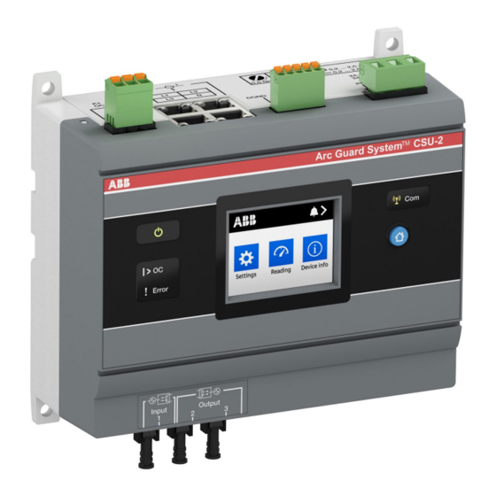
- Page 15 ARC GUARD SYSTEM™ – CSU-2LV/2MV INSTALL ATION AND MAINTENANCE GUIDE 3.2.1 CSU-2 The Current Sensing Unit (CSU-2) is an accessory needed in specific applications where strong light is expected on a regular basis. Current Sensing Units are connected with an optical cable using a light as signal for normal current.
- Page 16 ARC GUARD SYSTEM™ – CSU-2LV/2MV INSTALL ATION AND MAINTENANCE GUIDE 3.2.7 Current Sensors The current sensors are based on the principle of the Rogowski coil. The sensors consist of an air-core winding, immune to any risk of saturation as they have no ferromagnetic core.
- Page 17 ARC GUARD SYSTEM™ – CSU-2LV/2MV INSTALL ATION AND MAINTENANCE GUIDE...
- Page 19 ARC GUARD SYSTEM™ – CSU-2LV/2MV INSTALL ATION AND MAINTENANCE GUIDE — 4 Installation Introduction Installation procedure 4.2.1 Getting started 4.2.2 Mounting CSU-2 4.2.3 Configurations Setting the system 4.3.1 Start-Up Sequence 4.3.2 Controlling...
- Page 20 ARC GUARD SYSTEM™ – CSU-2LV/2MV INSTALL ATION AND MAINTENANCE GUIDE Introduction 4.2.1 Getting started This chapter describes how to install the CSU-2 and set up This section describes instructions on how to receive and the system. check the CSU-2. The installation of CSU-2 is performed in steps. After Do the following steps: finishing one step you proceed to the next one.
- Page 21 ARC GUARD SYSTEM™ – CSU-2LV/2MV INSTALL ATION AND MAINTENANCE GUIDE 4.2.2 Mounting CSU-2 This section describes the procedure to mount the CSU-2. The procedure is divided into the following components: • CSU-2 • Current Sensors Placing CSU-2 The CSU-2 can be mounted anywhere in the switchgear, for example in the breaker cubicle or in a separate control cabinet.
- Page 22 ARC GUARD SYSTEM™ – CSU-2LV/2MV INSTALL ATION AND MAINTENANCE GUIDE Mounting and connecting the CSU-2 to the system This is a summary of the complete procedure in mounting and connecting the CSU-2. WARNING Make sure that the supply voltage is switched...
- Page 23 ARC GUARD SYSTEM™ – CSU-2LV/2MV INSTALL ATION AND MAINTENANCE GUIDE Connecting optical cables WARNING Make sure that the supply voltage is switched off! Follow these steps to connect the optical cables. Remove the protection plug. Connect optical cables to the lower left side of CSU-2.
- Page 24 ARC GUARD SYSTEM™ – CSU-2LV/2MV INSTALL ATION AND MAINTENANCE GUIDE Connecting Modbus 24 ... 13 AWG 0,2 ... 2,5 mm WARNING 24 ... 13 AWG 0,2 ... 2,5 mm Make sure that the supply voltage is switched off! DGND -(A) +(B) Follow these steps to connect the Modbus, see Figure 8.
- Page 25 ARC GUARD SYSTEM™ – CSU-2LV/2MV INSTALL ATION AND MAINTENANCE GUIDE For the CSU-2MV, use current sensors 1VL5400076V0101 or 1VL5400056V10*. To mount current sensors 1VL5400076V0101, see Figure 11 and follow the steps below: Release the current sensor snap-lock. Open the current sensor.
- Page 26 ARC GUARD SYSTEM™ – CSU-2LV/2MV INSTALL ATION AND MAINTENANCE GUIDE 4.2.3 Configurations Power on the CSU-2 WARNING Working with high voltage is potentially lethal. Before switching the power supply on, follow the steps below: Check your installation. Check that electrical connections are orderly connected.
- Page 27 ARC GUARD SYSTEM™ – CSU-2LV/2MV INSTALL ATION AND MAINTENANCE GUIDE Setting the system This chapter describes the eight mandatory steps to succeed in setting the system. All settings are done in the Human Machine Interface, HMI. Settings are made only with the power on.
- Page 28 ARC GUARD SYSTEM™ – CSU-2LV/2MV INSTALL ATION AND MAINTENANCE GUIDE 4.3.2 Controlling INFORMATION Do the test after installation and before the CSU-2 is used! This test is done for each installed current sensor and the CSU-2. The test will check that...
- Page 29 ARC GUARD SYSTEM™ – CSU-2LV/2MV INSTALL ATION AND MAINTENANCE GUIDE...
- Page 31 ARC GUARD SYSTEM™ – CSU-2LV/2MV INSTALL ATION AND MAINTENANCE GUIDE — 5 Human Machine Interface (HMI) Introduction Menu flow chart Menu description 5.3.1 Settings 5.3.2 Reading 5.3.3 Device info 5.3.4 Events...
- Page 32 ARC GUARD SYSTEM™ – CSU-2LV/2MV INSTALL ATION AND MAINTENANCE GUIDE Introduction After power interruptions the Time and Date are set to a default value and needed to be set by the user. The HMI is accessed through the touchscreen. In the main menu, touch the symbols to reach the subcategories.
- Page 33 ARC GUARD SYSTEM™ – CSU-2LV/2MV INSTALL ATION AND MAINTENANCE GUIDE Menu flow chart Startup settings Main menu...
- Page 34 ARC GUARD SYSTEM™ – CSU-2LV/2MV INSTALL ATION AND MAINTENANCE GUIDE Menu description The main menu is structured in four head categories. Each category is divided into subcategories. Some subcategories have sub-sub categories. All categories are numbered accordingly to the structure. For more information, see “5.2 Menu flow chart”...
- Page 35 ARC GUARD SYSTEM™ – CSU-2LV/2MV INSTALL ATION AND MAINTENANCE GUIDE 5.3.2 Reading Reading shows the current reading for L1, L2, L3 or N (depending on settings). It also shows the settings for warning and over current. 5.3.3 Device info Device info shows information about: •...
- Page 36 ARC GUARD SYSTEM™ – CSU-2LV/2MV INSTALL ATION AND MAINTENANCE GUIDE 5.3.4 Events Events consist of the following subcategories: • Combined • Over current • Current warning • Error • Parameter change Over current events Over current detected by one or more of the connected Figure 23 current sensors.
- Page 37 ARC GUARD SYSTEM™ – CSU-2LV/2MV INSTALL ATION AND MAINTENANCE GUIDE Error events The system is continuously monitored for internal and external errors. Each detected error is stored with time and name of the error. See “Table 8 List of errors” on page 73 for a full list of possible errors.
- Page 39 ARC GUARD SYSTEM™ – CSU-2LV/2MV INSTALL ATION AND MAINTENANCE GUIDE — 6 Modbus Introduction References Quick start-up Installation 6.4.1 General 6.4.2 Connector 6.4.3 Cables 6.4.4 Termination Configuration Functional description 6.6.1 Implementation class 6.6.2 Supported Modbus functions 6.6.3 Register data format 6.6.4...
- Page 40 ARC GUARD SYSTEM™ – CSU-2LV/2MV INSTALL ATION AND MAINTENANCE GUIDE Installation Introduction This chapter covers the Modbus interface, which offers a direct connection to Modbus-RTU for the CSU-2. 6.4.1 General CSU-2 will behave as a slave. This means all communication...
- Page 41 ARC GUARD SYSTEM™ – CSU-2LV/2MV INSTALL ATION AND MAINTENANCE GUIDE 6.4.4 Termination For the best quality of data transfer, Modbus should be terminated correctly. The following figure shows the Modbus installation: Master Pull Up Balanced Pair Pull Down Common Slave 1...
- Page 42 ARC GUARD SYSTEM™ – CSU-2LV/2MV INSTALL ATION AND MAINTENANCE GUIDE Configuration Select Baud rate according to the existing network. On delivery the default value for Baud rate is 19200. Modbus configuration is done via the HMI. Access the Modbus configuration page by first selecting Settings on the Main page.
- Page 43 ARC GUARD SYSTEM™ – CSU-2LV/2MV INSTALL ATION AND MAINTENANCE GUIDE Functional description The information found here is the basic information needed for the installation of CSU-2 in a Modbus system. 6.6.1 Implementation class The physical and data link layers are implemented conforming to the “basic slave”...
- Page 44 ARC GUARD SYSTEM™ – CSU-2LV/2MV INSTALL ATION AND MAINTENANCE GUIDE Available registers 6.6.2.3 Modbus registers are numbered from 1 to 65536. In a Modbus PDU (Protocol Data Unit) these registers are addressed from 0 to 65535. The following table lists the available parameters. More details about the data format can be found in “6.6.3...
- Page 45 ARC GUARD SYSTEM™ – CSU-2LV/2MV INSTALL ATION AND MAINTENANCE GUIDE Modbus registers Parameter name Access Register Number Remark ERROR_ACTIVATE_YEAR_MONTH_1 0x92 Error 1 activate time year/month ERROR_ACTIVATE_DATE_HOUR_1 0x93 Error 1 activate time date/hour ERROR_ACTIVATE_MINUTE_SECOND_1 0x94 Error 1 activate time minute/second ERROR_ACTIVATE_YEAR_MONTH_2...
- Page 46 ARC GUARD SYSTEM™ – CSU-2LV/2MV INSTALL ATION AND MAINTENANCE GUIDE Modbus registers Parameter name Access Register Number Remark CW_MINUTE_SECOND_6 0xC7 Current warning 6 minute/second CW_INPUT_INFO_7 0xC8 Current warning 7 input info CW_YEAR_MONTH_7 0xC9 Current warning 7 year/month CW_DATE_HOUR_7 0xCA Current warning 7 date/hour...
- Page 47 ARC GUARD SYSTEM™ – CSU-2LV/2MV INSTALL ATION AND MAINTENANCE GUIDE Modbus registers Parameter name Access Register Number Remark ERROR_MINUTE_SECOND_9 0xFB Error 9 minute/second ERROR_TYPE_10 0xFC Error 10 type ERROR_YEAR_MONTH_10 0xFD Error 10 year/month ERROR_DATE_HOUR_10 0xFE Error 10 date/hour ERROR_MINUTE_SECOND_10 0xFF...
- Page 48 ARC GUARD SYSTEM™ – CSU-2LV/2MV INSTALL ATION AND MAINTENANCE GUIDE Modbus registers Parameter name Access Register Number Remark PARAM_CHANGE_YEAR_MONTH_10 0x12F Param. changed 10 year/month PARAM_CHANGE_DATE_HOUR_10 0x130 Param. changed 10 date/hour PARAM_CHANGE_MINUTE_SECOND_10 0x131 Param. changed 10 minute/second SW_VERSION_XXYY 0x132 SW version XX YY...
- Page 49 ARC GUARD SYSTEM™ – CSU-2LV/2MV INSTALL ATION AND MAINTENANCE GUIDE 6.6.3 Register data format This section describes details about the data format for selected registers. Read or read/write rights of the register are specified with (R) and (RW) respective. System status 6.6.3.1...
- Page 50 ARC GUARD SYSTEM™ – CSU-2LV/2MV INSTALL ATION AND MAINTENANCE GUIDE Active errors 6.6.3.3 Currently active errors, bit is set if error is active. ACTIVE_ERRORS 0x65 15–10 Internal Internal Internal Internal Input 1 Input 1 no Rogowski Rogowski Rogowski Rogowski error...
- Page 51 ARC GUARD SYSTEM™ – CSU-2LV/2MV INSTALL ATION AND MAINTENANCE GUIDE Parameter name Register access Remark ERROR_ACTIVATE_MINUTE_SECOND_1 0x94 (R) Rogowski coil L1 ERROR_ACTIVATE_MINUTE_SECOND_2 0x97 (R) Rogowski coil L2 ERROR_ACTIVATE_MINUTE_SECOND_3 0x9A (R) Rogowski coil L3 ERROR_ACTIVATE_MINUTE_SECOND_4 0x9D (R) Rogowski coil N ERROR_ACTIVATE_MINUTE_SECOND_5...
- Page 52 ARC GUARD SYSTEM™ – CSU-2LV/2MV INSTALL ATION AND MAINTENANCE GUIDE Activation times for over current events. If event never has occurred the register is set to 0xFFFF. Parameter name Register access Remark OC_YEAR_MONTH_1 0x6B (R) OC_YEAR_MONTH_2 0x6F (R) OC_YEAR_MONTH_3 0x73 (R)
- Page 53 ARC GUARD SYSTEM™ – CSU-2LV/2MV INSTALL ATION AND MAINTENANCE GUIDE Current warning events 6.6.4.2 The 10 last current warning events in chronological order, newest event on index #1. One or more phases and/or neutral that triggered the event. If event never has occurred the register is set to 0xFFFF.
- Page 54 ARC GUARD SYSTEM™ – CSU-2LV/2MV INSTALL ATION AND MAINTENANCE GUIDE Parameter name Register access Remark CW_MINUTE_SECOND_1 0xB3 (R) CW_MINUTE_SECOND_2 0xB7 (R) CW_MINUTE_SECOND_3 0xBB (R) CW_MINUTE_SECOND_4 0xBF (R) CW_MINUTE_SECOND_5 0xC3 (R) CW_MINUTE_SECOND_6 0xC7 (R) CW_MINUTE_SECOND_7 0xCB (R) CW_MINUTE_SECOND_8 0xCF (R) CW_MINUTE_SECOND_9...
- Page 55 ARC GUARD SYSTEM™ – CSU-2LV/2MV INSTALL ATION AND MAINTENANCE GUIDE Activation times for over error events. If event never has occurred the register is set to 0xFFFF. Parameter name Register access Remark ERROR_YEAR_MONTH_1 0xD9 (R) ERROR_YEAR_MONTH_2 0xDD (R) ERROR_YEAR_MONTH_3 0xE1 (R)
- Page 56 ARC GUARD SYSTEM™ – CSU-2LV/2MV INSTALL ATION AND MAINTENANCE GUIDE Parameter change events 6.6.4.4 The 10 last parameter change events in chronological order, newest event on index #1. If event never has occurred the register is set to 0xFFFF. Parameter...
- Page 57 ARC GUARD SYSTEM™ – CSU-2LV/2MV INSTALL ATION AND MAINTENANCE GUIDE Setting of the changed parameter, possible setting values: Parameter Setting Values First setup (Not done) (Done) Modbus id 0-248 Modbus baud rate (9600) (19200) (38400) (57600) Modbus frame format (8 bits, even parity, 1 stop bit)
- Page 58 ARC GUARD SYSTEM™ – CSU-2LV/2MV INSTALL ATION AND MAINTENANCE GUIDE Activation times for parameter change events. If event never has occurred the register is set to 0xFFFF. Parameter name Register access Remark PARAM_CHANGE_YEAR_MONTH_1 0x102 (R) PARAM_CHANGE_YEAR_MONTH_2 0x107 (R) PARAM_CHANGE_YEAR_MONTH_3 0x10C (R)
- Page 59 ARC GUARD SYSTEM™ – CSU-2LV/2MV INSTALL ATION AND MAINTENANCE GUIDE Unit information 6.6.4.5 Software version The software version is specified with three numbers XX.YY.ZZ. The version is presented using two registers. Parameter name Register access SW_VERSION_XXYY 0x132 (R) Version no. XX Version no.
- Page 60 ARC GUARD SYSTEM™ – CSU-2LV/2MV INSTALL ATION AND MAINTENANCE GUIDE Modbus parameters Parameters defining the Modbus settings. Modbus id in range 0 – 248. Parameter name Register access MODBUS_DEVICE_ID 0x142 (R) Device id Modbus baud rate (9600) (19200) (38400) (57600)
- Page 61 ARC GUARD SYSTEM™ – CSU-2LV/2MV INSTALL ATION AND MAINTENANCE GUIDE Configuration parameters 6.6.4.6 Parameters defining active inputs and levels. Input configuration Current measurement inputs (L1) (L1 L2) (L1 L2 L3) (L1 L2 L3 Neutral) Parameter name Register access INPUT_CONFIGURATION 0x14E (RW) Correction factors Amplitude correction factor (aI).
- Page 62 ARC GUARD SYSTEM™ – CSU-2LV/2MV INSTALL ATION AND MAINTENANCE GUIDE Daisy chain Enable or disable daisy chain functionality. Current measurement inputs (ON) (OFF) Parameter name Register access DAISY_CHAIN_STATUS 0x14F (RW) Date and time 6.6.4.7 System date and time Parameter name...
- Page 63 ARC GUARD SYSTEM™ – CSU-2LV/2MV INSTALL ATION AND MAINTENANCE GUIDE Reset 6.6.4.8 Reset of over current and current warning Command (NOT_USED) (RESET) Parameter name Register access RESET_OVER_CURRENT 0x15B (RW) RESET_CURRENT_WARNING 0x15C (RW) Spare 6.6.4.9 Empty registers. Parameter name Register access...
- Page 64 ARC GUARD SYSTEM™ – CSU-2LV/2MV INSTALL ATION AND MAINTENANCE GUIDE Troubleshooting 6.7.1 Visual diagnostics The yellow Com LED flashes when a Modbus request is received. 6.7.2 Practice via modpoll [3] Using the application modpoll [3] from a windows environment, it is easy to communicate with CSU-2. To...
- Page 65 ARC GUARD SYSTEM™ – CSU-2LV/2MV INSTALL ATION AND MAINTENANCE GUIDE 6.7.3 Practice via PLC This section shows a demo about how to read system status using a Programmable logic controller (PLC). We use AC500 and Automation Builder as a development platform.
- Page 66 ARC GUARD SYSTEM™ – CSU-2LV/2MV INSTALL ATION AND MAINTENANCE GUIDE...
- Page 67 ARC GUARD SYSTEM™ – CSU-2LV/2MV INSTALL ATION AND MAINTENANCE GUIDE — 7 Maintenance Introduction...
- Page 68 ARC GUARD SYSTEM™ – CSU-2LV/2MV INSTALL ATION AND MAINTENANCE GUIDE Introduction The Arc Guard System™ CSU-2 does not require any special maintenance due to that it continuously monitors itself. For maintenance of the Arc Guard System™ see SFC170011M0201, Arc Guard System™ – TVOC-2...
- Page 69 ARC GUARD SYSTEM™ – CSU-2LV/2MV INSTALL ATION AND MAINTENANCE GUIDE...
- Page 71 ARC GUARD SYSTEM™ – CSU-2LV/2MV INSTALL ATION AND MAINTENANCE GUIDE — 8 Troubleshooting Introduction Requirements Error events 8.3.1 LED-lights 8.3.2 ABB support...
- Page 72 That includes the handling logged in the error event log, possible errors and actions error event log, list of error codes and how to contact ABB. upon them are presented in Table 8. The log can hold 10 events, once the log is full the oldest event will be removed upon arrival of a new event.
- Page 73 ARC GUARD SYSTEM™ – CSU-2LV/2MV INSTALL ATION AND MAINTENANCE GUIDE Table 8 List of errors Error code Description Recommended actions Ix LL Input x low light Degenerated LED at connected CSU-2/TVOC-2 unit. The unit in the other end should be replaced.
- Page 74 ARC GUARD SYSTEM™ – CSU-2LV/2MV INSTALL ATION AND MAINTENANCE GUIDE 8.3.2 ABB support If you have a problem with your CSU-2, contact ABB for support. Contact information ABB AB Control Products SE-721 61 VÄSTERÅS, Sweden Telephone +46 21 32 07 00 www.abb.com/lowvoltage...
- Page 75 ARC GUARD SYSTEM™ – CSU-2LV/2MV INSTALL ATION AND MAINTENANCE GUIDE...
- Page 77 ARC GUARD SYSTEM™ – CSU-2LV/2MV INSTALL ATION AND MAINTENANCE GUIDE — 9 Technical data Technical data Dimensions Applications, Diagrams 9.3.1 Example 1 9.3.2 Example 2 Circuit diagrams...
- Page 78 ARC GUARD SYSTEM™ – CSU-2LV/2MV INSTALL ATION AND MAINTENANCE GUIDE Technical data Table 11 Technical data Common technical data Overvoltage category Pollution degreee Power supply CSU-2 Rated supply voltage,U s 24-240 V AC 50-60 Hz 24-250 V DC U s variation...
- Page 79 ARC GUARD SYSTEM™ – CSU-2LV/2MV INSTALL ATION AND MAINTENANCE GUIDE Dimensions Current sensor unit 155.5 63.8 141.1 Ø5.5 46.4 28.5 2 x 14 Drilling plan For M5...
- Page 80 ARC GUARD SYSTEM™ – CSU-2LV/2MV INSTALL ATION AND MAINTENANCE GUIDE Applications Diagrams 9.3.1 Example 1 Example 1: Arc Guard System™ configured to trip all contacts in case of an arc and over current. Table 12 Connection description for example 1...
- Page 81 ARC GUARD SYSTEM™ – CSU-2LV/2MV INSTALL ATION AND MAINTENANCE GUIDE 9.3.2 Example 2 Example 2: Arc Guard system™ configured to trip different trip contacts depending on where the arc occurs together with over current. Table 13 Connection description for example 2...
- Page 82 ARC GUARD SYSTEM™ – CSU-2LV/2MV INSTALL ATION AND MAINTENANCE GUIDE Circuit diagrams Arc Monitor K1 OC L1 L2 L3 DGND -(A) ≥ I + (B) ≥ I ≥ I ≥ I A2 PE CSU-2LV/MV 1SFA664002R5001 / 1SFA664002R8001 A6641001R1002 Table 14...
- Page 83 ARC GUARD SYSTEM™ – CSU-2LV/2MV INSTALL ATION AND MAINTENANCE GUIDE...
- Page 84 We reserve the right to make technical changes or modify the contents of this document without prior notice. ABB does not accept any responsibility whatsoever for potential errors or possible lack of information in this document. We reserve all rights in this document and in the subject matter and illustrations contained therein.
Need help?
Do you have a question about the CSU-2LV and is the answer not in the manual?
Questions and answers