Table of Contents
Advertisement
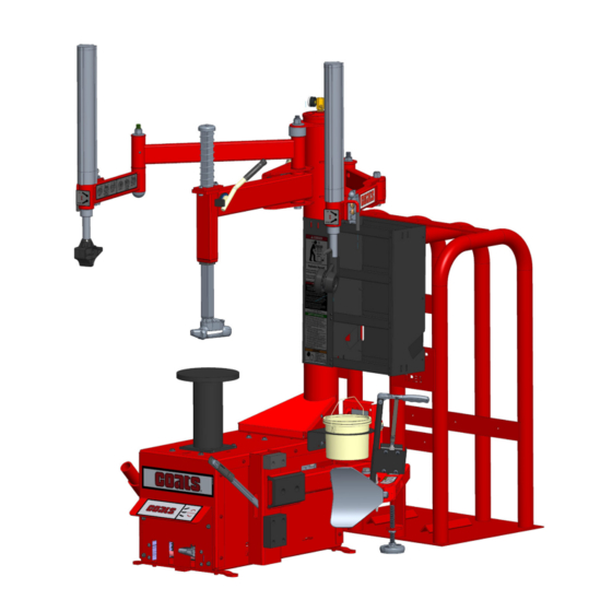
80C Model
Center Clamp Tire Changer
For servicing single piece
automotive and most tubeless light
truck tire/wheel assemblies.
Any other type, including tube type agricultrual,
require special handling. Tires identified as truck
tires need to adhere to OSHA standard 1910.177.
See
RIM Safety
Operating
Instructions
on page 4.
1601 J. P . Hennessy Drive, LaVergne, TN USA 37086
HENNESSY INDUSTRIES LLC Manufacturer of COATS
page 1
Operation Instructions
Maintenance Instructions
READ these instructions before placing unit in
service. KEEP these and other materials delivered
with the unit in a binder near the machine for ease
of reference by supervisors and operators.
615/641-7533
800/688/6359
, AMMCO
and BADA
®
®
Safety Instructions
Set-up Instructions
www.coatsgarage.com
Automotive Service Equipment and Tools.
®
Shown with optional
EL-X Express Lane
®
Inflation System
(part # 85607770)
Manual Part No.:
85611918 00
Revision:
8/20
Advertisement
Table of Contents

Related Manuals for Coats 80C


Summary of Contents for Coats 80C
- Page 1 1601 J. P . Hennessy Drive, LaVergne, TN USA 37086 615/641-7533 800/688/6359 www.coatsgarage.com Manual Part No.: 85611918 00 HENNESSY INDUSTRIES LLC Manufacturer of COATS , AMMCO and BADA Automotive Service Equipment and Tools. Revision: 8/20 ®...
-
Page 2: Table Of Contents
Table of Contents Tire Specifications Diagram ......iii Custom and Special Wheels ......16 Safety Instructions ..........iv Tube Type Tires ..........16 Owner’s Responsibility ........iv Maintenance Instructions .........17 Operator Protective Equipment ......iv Duckhead (Mount/Demount Tool) Cleaning ..17 Definitions of H azard Levels ......iv Duckhead (Mount/Demount Tool) Adjustment ............18 Safety Notices and Decals ........ -
Page 3: Tire Specifications Diagram
Tire Specifications Diagram Tire Specification Radial Rim diameter code Ratio of height to Load index & width (aspect ratio) speed symbol Nominal width of tire in millimeters U.S. DOT tire identification number Passenger car tire Severe snow conditions Max. Tire ply permissible composition inflation... -
Page 4: Safety Instructions
Safety Instructions Definitions of Hazard Levels Identify the hazard levels used in this manual with Owner’s Responsibility the following definitions and signal words: To maintain machine and user safety, the responsibil- DANGER ity of the owner is to read and follow these instruc- Watch for this symbol: tions: •... -
Page 5: Safety Notices And Decals
Tire Guides, Inc. The Tire Information Center 1101-6 South Rogers Circle Boca Raton, FL 33487-2795 (561) 997-9229 www.tireguides.com For more details, contact your Coats distributor or e-mail us. Decal part number 85611138. Important: Always read and follow operating instructions. • 1... -
Page 6: Principle Operating Parts
Principal Operating Parts Know Your Unit Compare this illustration with the unit before placing Do It Now! it into service. Maximum performance and safety Now is a good time to contact product service at will be obtained only when all persons using the unit 800-688-6359 to start warranty, otherwise warranty are fully trained in its parts and operation. - Page 7 CAUTION Tower — Support for swing arm, Robo-Arm Replace any damaged or missing safety decals. They are available from COATS, helper device and RoboRoller™ powered assist, also (800) 688-6359. air storage tank. Pressure Safety Valve — The high pressure safety...
-
Page 8: Operating Instructions
Operating Instructions This unit must be properly operated and properly maintained to help avoid accidents that could injure the operator or bystanders, or damage the unit. This section of the Operating Instructions manual review basic operations and use of controls. These instructions should be reviewed with all employees before they are allowed to work with the machine. - Page 9 5. Place rubber protective cover on top of pedestal (reverse mount only). Align slot with anti-rotation pin. Figure 6 - Place Protective Cover on Pedestal Figure 3 - Position Tire and Bead Loosener Shoe with Valve Stem in 2 o’clock Position. 6.
- Page 10 7. Place tire/wheel assembly on pedestal with the 8. Place the center mount lock shaft through center mounting side up (see figures 8a and 8c) and with the of wheel (figure 9). Push it down and turn 90-degrees anti-rotation pin located inside one of the lug holes. clockwise to clamp wheel to pedestal (figure 10).
- Page 11 10. The mount/demount tool should be in contact 12. Check plastic tool positioning. Mount/demount with the rim edge. Turn the swing arm adjusting knob plastic tool should be positioned with 1/16 to 1/8 to move the mount/demount tool away from the rim inch clearance between the top of the rim edge and 1/8 to 1/4 inch (figure 12).
- Page 12 16. Depress the rotation pedal to rotate the wheel. CAUTION The Duckhead mount/demount tool will guide the tire bead up and over the edge of the wheel. Continue rotation until the upper bead is demounted. times during mounting demounting procedure, the bead lifting NOTE: Push down on the tire across from the tool may encounter resistance and can be demount tool during pedestal rotation to utilize...
-
Page 13: Tire Mounting
Tire Mounting 1. Before any mounting, inspect tire for damage and verify size match between tire and wheel (figure 20). This information must be read and followed carefully to prevent accidents and injuries during mounting. Mounting a mismatched tire and wheel will cause an explosion before it bead seats during inflation. - Page 14 4. Place tire over wheel and move swing arm into 6. Use Robo-Arm helper device to push down on ® position making sure the valve stem is at the 9 o’clock tire 90 degrees clockwise from Duckhead mount/ position in front of bead lock. Position tire so that demount tool to allow bead to utilize drop center area lower bead is above the rear extension of the mount/ of rim (figure 25).
-
Page 15: Inflation
Inflation The inflation pedal, located at the rear of the left side of the machine, controls the flow of air through the Tire inflation is performed in three steps: BEAD inflation hose, and has two positions. SEAL, BEAD SEAT, and INFLATION. These steps are Note: The clip-on chuck on the end of the hose is explained in detail on page 14. -
Page 16: Bead Sealing
Bead Sealing Bead Seating 1. Remove the valve core from the valve stem to allow more air flow into the tire to assist with bead seal. NEVER exceed 40 PSI to seat beads while 2. Position valve stem in front of operator and con- using this tire changer. -
Page 17: Inflation
Inflation NEVER exceed tire manufacturer's recom- mended air pressure. Tires can explode, especially if inflated beyond these limits. Use clip-on air chuck, keep hands, arms and entire body back from inflating tire. Avoid distraction during inflation. Check tire pressure frequently to avoid over infla- tion. -
Page 18: Stages Of Inflation On A Conventional Tire And Rim
Stages of Inflation on a Conventional Tire and Rim Review these descriptions and diagrams carefully. Refer to them as necessary during bead sealing, bead seating, and inflation to verify that you are proceeding properly and safely. Bead Sealing Bead sealing is the process of capturing air pressure between the tire and the rim. -
Page 19: Mismatched Tires And Wheels
Mismatched Tires and Wheels Never mount and inflate mis-matched tires and wheels. Mismatched tire and wheel combinations will explode, if you attempt to force a bead seat, causing personal injury or death to operator and/or bystanders. Important: Always read and follow operating instructions. •... -
Page 20: Custom And Special Wheels
Custom and Special Wheels Tube Type Tires Mounting CAUTION 1. Avoid pinching or forcing the tube. 2. Apply rubber lubricant to the beads of the tire. Only tire technicians with experience and 3. Mount the bottom bead. training on custom wheels should attempt to service expensive custom alloy or alu- 4. -
Page 21: Maintenance Instructions
If necessary, adjust the dial of the machine gauge. If the gauge is defective, replace it imme- diately (part number 8107985). Contact COATS at (615) 641-7533. Check function of the pressure limiter weekly. Always reinstall the lens after adjusting the gauge. -
Page 22: Duckhead (Mount/Demount Tool) Adjustment
Helper Arm Maintenance Duckhead (Mount/Demount Tool) Robo-Arm Helper Device Maintenance ® Adjustment 1. Grease helper arms to maintain smooth rotation. Grease fittings have been provided at the pivot joints. To Adjust Tool Head Lift Shoulder screw (ref.1) sets the tool head lift for 2. -
Page 23: Pressure Limiter Maintenance
Pressure Limiter Maintenance 4. Watch the rising pressure on the tank gauge and the gauge on the machine. Machine gauge should cycle between check and inflation pressures while tank gauge climbs steadily. As tank pressure reaches 60 PSI, the pressure limiter should stop the airflow Operating a tire changer with a defective, automatically. -
Page 24: Separator/Lubricator Maintenance
Separator/Lubricator Maintenance 4. Adjust the oil flow by turning the black flow adjustment knob and turning it to increase or decrease Check oil and water levels regularly, and perform the flow. Watch the formation of oil drops in the these maintenance items weekly: see-through oil chamber. -
Page 25: Setup Instructions
Setup Instructions Air Source The all-air models require a 14 to 15 CFM air source CAUTION at 150 PSI. The air/electric models require a 5 CFM air source at 150 PSI. The operating pressure range for all models is between 110 PSI and 175 PSI at the Proper unit installation is necessary for machine. - Page 26 Notes 22 • Important: Always read and follow operating instructions.
- Page 27 Notes Important: Always read and follow operating instructions. • 23...
- Page 28 AFETY R.I.M. READ INSPECT MOUNT READ… INSPECT… MOUNT… Mounting and inflating the Before you put any tire Once you’ve made sure the tire is OK wrong size tire can get on a rim, inspect the rim and the right size and the rim is OK, you hurt.
Need help?
Do you have a question about the 80C and is the answer not in the manual?
Questions and answers