Table of Contents
Advertisement
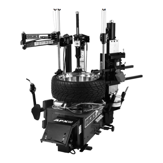
APX80A/APX80E
APX90A/APX90E
Rim Clamp
For servicing single piece automotive and most light truck
tire/wheel assemblies
* APX 90 Shown
See
RIM Safety page iv
¨Operating
Instructions
page 4
Unload Instructions
page 18
1601 J. P. Hennessy Drive, LaVergne, TN USA 37086-3565 615/641-7533 800/688-6359
HENNESSY INDUSTRIES INC. Manufacturer of AMMCO
®
Tire Changer
Installation Instructions
Operating Instructions
Safety Instructions
Maintenance Instructions
READ these instructions before placing unit in
service KEEP these and other materials delivered
with the unit in a binder near the machine for
ease of reference by supervisors and operators.
®
, COATS
®
and BADA
®
Automotive Service Equipment and Tools.
Manual Part No.: 85000226 11
Revision:
06/17
Advertisement
Table of Contents


Need help?
Do you have a question about the Rim Clamp APX80E and is the answer not in the manual?
Questions and answers