Table of Contents
Advertisement
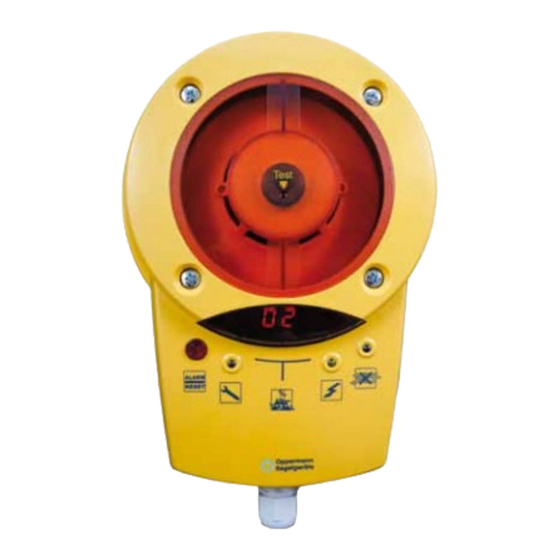
Duct Smoke Detector KRM®
Technical Data
Sensor:
Scattering RM 3.3 (ALK-E)
Supply voltage KRM-1: 230 V AC ± 10 %, 50/60 Hz
Supply voltage KRM-2/KRM-2-MOD:
24 V AC/DC +15 % / -10 %
Rated current:
KRM-1: 30 mA
KRM-2/KRM-2-MOD: 120 mA
Relay outputs:
floating
Alarm relay locked:
1 changeover contact, 8 A,
250 V AC or 24 V DC
1 NC, 8 A, 250 V AC or 24 V DC
Contamination relay:
1 NC contact, 6 A, 250 V AC or 24 V DC
Operating temperature: -20 °C – +50 °C
Permissible flow:
1 – 20 m/s
Permissible humidity:
10 – 95 % non-condensing
Protection class:
IP54, IP65 with WDG
(water resistant housing)
Certification/approvals: VdS approval G210059
according to FprEN54-27
LED display:
% contamination level flashes
at > 70 %
LED in housing:
green operating
blue
yellow failure, electronics,
red
Adapter housing:
ABS
Air measuring tube:
Aluminium / plastic
shortest length 160 mm
standard length 600 mm
Dimensions:
257 x 166 x 77 mm (L x W x H)
Screw connection:
3 x M16
lack of air flow
smoke detector defective,
low voltage
smoke alarm, including
contamination > 99 %,
flashes at attempts to release
when the sensing chamber is
not empty
•
VdS certification (G210059)
•
Patented single tube air sampling system
•
Contamination display in %
and signalling at 100 %
•
Electronic air flow control
•
Externally operable reset button in the
housing
•
Remote reset option via terminals
•
Long service life, low contamination
•
Modbus interface (KRM-2-MOD only)
Accessories
Mounting bracket:
KS (for insulated / circular ducts)
KS-WDG (for insulated / circular ducts in
combination with WDG)
Housing:
WDG – waterresistant housing for
outdoor installation and increasing
protection class to IP65
Function
The KRM duct smoke detector is designed for smoke detection in
ventilation ducts. It constitutes a combination of a smoke detec-
tor with an adapter system, whose measuring tube and housing
have been specially adapted for optimal air flow through the
smoke detector.
The multi-chamber measuring tube in the air duct transports the
air within the air duct along the entire length of the tube, through
the sensing chamber and back into the air duct. Upon detection
of smoke, the sensor reacts immediately and triggers an alarm.
Over time, the sensor becomes contaminated. Because of alarm
threshold tracking, the sensitivity up to total pollution remains
the same. From 70 % contamination upwards, the sensor is trig-
gered and indicates this by flashing. If the sensor is not replaced
the smoke alarm is triggered at 99 % contamination. The contami-
nation level is indicated in a two-line LED display; at > 70 % it
flashes.
To verify operability, the device is equipped with electronic air
flow monitoring, which lights a blue LED at < 1 m/s. The failure
LED illuminates when the smoke sensor or the electronics are
defective, and in the absence of a smoke detector.
The smoke alarm must be released with the reset button.
A functionality test is also possible with the same button.
The operation functions like a smoke alarm.
Furthermore, the same function takes place on restart or when
the bridge circuit between terminals 9 and 10 is opened (remote
release).
Fire Protection | Data sheet No. 41300 | Version 06-2012 | 1 | 9
Advertisement
Table of Contents

Related Manuals for Oppermann Regelgeräte KRM


Summary of Contents for Oppermann Regelgeräte KRM
- Page 1 1 NC contact, 6 A, 250 V AC or 24 V DC Function Operating temperature: -20 °C – +50 °C Permissible flow: 1 – 20 m/s The KRM duct smoke detector is designed for smoke detection in Permissible humidity: 10 – 95 % non-condensing ventilation ducts. It constitutes a combination of a smoke detec- Protection class:...
-
Page 2: Electrical Connection
A mixed connection of safety extra-low voltage (SELV) and low voltage must not occur. The assembly may only be operated on one mains phase. The voltage / safeguard activation is to be provided on site. KRM-1-xx (230 V versions) with a fuse of 16 A;... - Page 3 Duct Smoke Detector KRM Display and operation for Duct Smoke Sensor KRM LED Smoke alarm (red) LED Smoke alarm (red) Display indicator (contamination in % or status) LED Failure (yellow) LED Power supply (green) LED Alarm (red) and LED Air flow (blue)
- Page 4 Do not release it until then. KRM will start again only after release. As long as the alarm / reset LED flashes when the button is pressed, the smoke sensor is still filled with test gas / test spray / smoke, and can not be reset.
- Page 5 The distance of guidelines, etc.) are to be observed. Installers and operators are the KRM to fittings, valves, filters, etc. in terms of flow direc- required to be adequately informed before operation. Read the tion should be 3 times, and in the diagonal direction 5 times product description before device start-up.
-
Page 6: Installation
Duct Smoke Detector KRM min. 160 mm Installation Drill a hole 43 – 44 mm in diameter at the intended mounting location. Note: Installation of the TurboTube measuring tube is possible either from the top, bottom or side of the channel for all duct cross-sections (for round ducts as well). - Page 7 Duct Smoke Detector KRM 8. Installing the housing with the sensor • Attach the housing bottom part with the electronics and sensor to the adapter plate. The housing can be attached at increments of 90°. The direction of the housing has no effect on the measurement result. You can align the housing with the sensor optimally.
-
Page 8: Instructions For Operation And Maintenance
Duct Smoke Detector KRM Maintenance and repair Caution: Before opening the housing, unlock all supply voltages – The housing may only be opened by a qualified electrician. Supply 1. Instructions for operation and and switching voltages must be observed. maintenance Please note the symbols on the device: The operator is responsible for the safe function of the ventila- tion system. - Page 9 • Release is possible by pressing the reset button (types: KRM-1-DZ, KRM-2-DZ and KRM-2-DZ-MOD) or with brief power interruptions (only for types KRM-1, KRM-2, KRM-2-MOD) • Release and approve for operation. Dimensions L= min.
-
Page 10: Drilling Template
Drilling template Dimensions in mm...
Need help?
Do you have a question about the KRM and is the answer not in the manual?
Questions and answers