Table of Contents
Advertisement
Quick Links
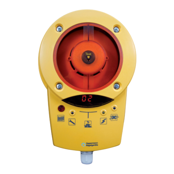
Duct Smoke Sensor KRM®
Technical Data
Sensor:
Scattering RM 3.3 (ALK-E)
Supply voltage KRM-1:
230 V AC ± 10 %, 50/60 Hz
Supply voltage KRM-2/KRM-2-MOD:
24 V AC/DC +15 % / -10 %
Rated current:
KRM-1: 30 mA
KRM-2/KRM-2-MOD: 120 mA
Relay outputs:
floating
Alarm relay locked:
1 changeover contact, 8 A,
250 V AC or 24 V DC
1 NC, 8 A, 250 V AC or 24 V DC
Contamination relay:
1 NC contact, 6 A, 250 V AC or 24 V DC
Operating temperature: -10 °C - +50 °C
Permissible humidity:
10 - 95 % non-condensing
Protection class:
IP 54, IP 65 with WDG
(water resistant housing)
Approvals:
Sensing chamber and
air duct frames:
VdS approval G210059
Tested:
according to FprEN54-27
LED display:
% contamination level flashes
at > 70 %
LED in housing:
green operating
blue
yellow failure, electronics,
red
Adaptergehäuse:
ABS
Air measuring tube:
Aluminium / plastic
shortest length 160 mm
standard length 600 mm
Dimensions:
257 x 166 x 77 mm (L x W x H)
Screw connection:
3 x M16
lack of air flow
smoke detector defective,
low voltage
smoke alarm, including
contamination > 99 %,
flashes at attempts to release
when the sensing chamber is
not empty
•
VdS certification (G210059)
•
Patented single tube air sampling system
•
Contamination display in %
and signalling at 100 %
•
Electronic air flow control
•
Externally operable reset button in the
housing
•
Remote reset option via terminals
•
Long service life, low contamination
Accessories
Mounting bracket:
KS (for insulated / circular ducts)
Housing:
waterresistant housing for outdoor
installation and increasing protection
class to IP 65
Function
The KRM duct smoke detector is designed for smoke detection
in ventilation ducts. It constitutes a combination of a smoke
detector with an adapter system, whose measuring tube and
housing have been specially adapted for optimal air flow through
the smoke detector.
The multi-chamber measuring tube in the air duct transports the
air within the air duct along the entire length of the tube, through
the sensing chamber and back into the air duct. Upon detection
of smoke, the sensor reacts immediately and triggers an alarm.
Over time, the sensor becomes contaminated. Because of alarm
threshold tracking, the sensitivity up to total pollution remains
the same. From 70 % contamination upwards, the sensor is trig-
gered and indicates this by flashing. If the sensor is not replaced
the smoke alarm is triggered at 99 % contamination.
The contamination level is indicated in a two-line LED display; at
> 70 % it flashes.
To verify operability, the device is equipped with electronic air
flow monitoring, which lights a blue LED at < 1 m/s. The failure
LED illuminates when the smoke sensor or the electronics are
defective, in the absence of a smoke sensor, and with short-
circuits or cable breakage.
The smoke alarm must be released with the reset button.
A functionality test is also possible with the same button.
The operation functions like a smoke alarm.
Furthermore, the same function takes place on restart or when
the bridge circuit between terminals 9 and 10 is opened (remote
release).
Fire Protection | Data sheet No. 41300 | Version 01-2011 | 1 | 8
Advertisement
Table of Contents

Subscribe to Our Youtube Channel
Related Manuals for Oppermann Regelgeräte KRM-1


Summary of Contents for Oppermann Regelgeräte KRM-1
-
Page 1: Technical Data
Long service life, low contamination Technical Data Sensor: Scattering RM 3.3 (ALK-E) Accessories Supply voltage KRM-1: 230 V AC ± 10 %, 50/60 Hz Supply voltage KRM-2/KRM-2-MOD: Mounting bracket: KS (for insulated / circular ducts) 24 V AC/DC +15 % / -10 %... -
Page 2: Electrical Connection
Service signal Service signal Contamination Contamination yellow yellow blue blue KRM-1, 230 V KRM-2, 24 V KRM-2 KRM-1 Programming the Bus address for the KRM-2-Mod: Power supply Press buttons T3+T4 on the circuit board (to the right, next to the green... -
Page 3: Installation Instructions
Duct Smoke Sensor KRM Installation Instructions Accessories Install the detector where flow meters, etc. are normally fixed, Splash-proof housing (type so that the air flow can run in a laminar manner with the measu- WDG) for outdoor installation ring tube. Follow the installation instructions. All work must be to prevent condensation. - Page 4 Duct Smoke Sensor KRM • Determine the direction of flow and fit the adapter plate so that the line on the adapter plate under the text „Strömungsrichtung“ is parallel to the flow direction. • Four self-tapping screws serve for attaching it to the sheet metal duct (not included in delivery).
- Page 5 Duct Smoke Sensor KRM 9. Installing the housing with the sensor • Attach the housing bottom part with the electronics and sensor to the adapter plate. The housing can be attached at incre- ments of 90 °. The direction of the housing has no effect on the measurement result.
- Page 6 Duct Smoke Sensor KRM Display and operation for Duct Smoke Sensor KRM LED Smoke alarm (red) LED Smoke alarm (red) LED Failure (yellow) LED Power supply (green) LED Alarm (red) and LED Air flow (blue) Alarm / reset button Failure reset: Briefly press button and release Alarm reset: Press button for at least 2 seconds...
- Page 7 (TurboTube) for contamination / clean if necessary. Behavior of the alarm relay and fault relay and displays, plus reset options Smoke alarm Device failure / missing detector… DIBT versions KRM-1 / KRM-2 DIBT versions KRM-1 / KRM-2 KRM-1-DZ / KRM-2-DZ KRM-2-MOD...
- Page 8 Duct Smoke Sensor KRM Dimensions L= 160 - 3000 mm Dimensions in mm Oppermann Regelgeräte GmbH | Im Spitzhau 1 | 70771 Leinfelden-Echterdingen, Germany Phone +49 711 72 72 35 60 | Fax +49 711 72 80 52 7 | info@oppermann-regelgeraete.de | www.oppermann-regelgeraete.de 8 | 8 | Fire Protection | Data sheet No.
Need help?
Do you have a question about the KRM-1 and is the answer not in the manual?
Questions and answers