Advertisement
I. DESCRIPTION AND APPLICATION
As autonomous safety systems for intended use in hazardous areas the listed types comply with the
requirements of the European Directive 2014/34/EU and the harmonized standard for flame arrestors EN
ISO 16852.
This document applies to the following types according to the charts 1‐3. The limit values of the maximum
operating pressure p
, the maximum operating temperature T
0
source L
must be kept !
u
Ex‐ Gr.
Pipe size
DN15
(½")
DN20
(¾")
DN25
(1")
DN32
(1¼")
DN40
(1½")
DN50
(2")
IIA1
DN65
(2½")
DN80
(3")
DN100 (4")
DN125 (5")
DN150 (6")
DN200 (8")
Chart 1: Types of explosion group IIA1 (MESG > 1,14 mm) protect against deflagration and endurance burning
Ex‐ Gr.
Pipe size
DN20
(¾")
DN25
(1")
DN32
(1¼")
DN40
(1½")
DN50
(2")
DN65
(2½")
IIA1
DN80
(3")
DN100 (4")
DN125 (5")
DN150 (6")
DN200 (8")
DN250 (10")
DN300 (12")
Chart 2: Types of explosion group IIA1 (MESG > 1,14 mm) protect against deflagration and short time burning
maximum time of stabilized burning 1 minute
04/16
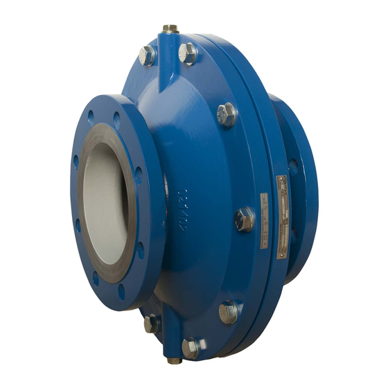
Installation, Operation and Maintenance Instructions
Model 6A00
Inline Deflagration Flame Arrestor
Chapter I
Type
p
0
[kPa(abs.)]
6A0A1
110
6A0B1
110
6A0C1
110
6A0K1
110
6A0U1
110
6A0V1
110
6A131
110
6A1B1
110
6A1K1
110
6A1T1
110
6A1U1
110
6A221
110
Type
p
0
[kPa(abs.)]
6A0B6
160
6A0C6
160
6A0K6
160
6A0U6
160
6A0V6
160
6A136
160
6A1B6
160
6A1K6
160
6A1T6
160
6A1U6
160
6A226
160
6A2A6
160
6A2H6
160
and the maximum distance to the ignition
0
T
L
EC‐type examination
0
u
[°C]
[m]
certificate
60
0,75
60
1,00
60
1,25
60
1,60
60
2,00
60
2,50
IBExU13ATEX2122 X
60
3,25
60
4,00
60
5,00
60
6,25
60
7,50
60
10,0
T
L
EC‐type examination
0
u
[°C]
[m]
certificate
60
1,00
60
1,25
60
1,60
60
2,00
60
2,50
60
3,25
60
4,00
IBExU13ATEX2148 X
60
5,00
60
6,25
60
7,50
60
10,0
60
12,5
60
15,0
IOM‐6A00 IIA1/IIA
02‐15
Page 1
Advertisement
Table of Contents

Related Manuals for cashco 6A00


Summary of Contents for cashco 6A00
- Page 1 Installation, Operation and Maintenance Instructions IOM‐6A00 IIA1/IIA 02‐15 Model 6A00 Inline Deflagration Flame Arrestor Chapter I I. DESCRIPTION AND APPLICATION As autonomous safety systems for intended use in hazardous areas the listed types comply with the requirements of the European Directive 2014/34/EU and the harmonized standard for flame arrestors EN ISO 16852. This document applies to the following types according to the charts 1‐3. The limit values of the maximum ...
- Page 2 Ex‐ Gr. Pipe size Type EC‐type examination [kPa(abs.)] [°C] [m] certificate DN20 (¾") 6A3Y6 160 60 1,00 DN25 (1") 6A3Z6 160 60 1,25 DN32 (1¼") 6A462 120 60 1,60 DN40 (1½") 6A4E2 120 60 2,00 DN50 (2") ...
- Page 3 Chapter II II. Safety Instructions The marking of the flame arrestor is carried out according to EN ISO 16852 respective their application. Each flame arrestor is marked with a nameplate and a warning sign. The nameplate as shown in figure 1 contains the following information: Fig. 1 2 7 1. Name and address of the manufacturer 2. Type designation 3. Number of the EC‐type examination certificate 4. Serial number / year of manufacture 5. Pipe size 6. Marking hazardous area „G“ for gas and vapor 7. Explosion group 8. Standard for flame arrester 9. CE‐marking with details of the named location ...
- Page 4 Chapter III III. TRANSPORT AND STORAGE The flame arrestor shall be packed carefully in order to prevent damages or impurity during the transport or storage. Chapter IV IV. INSTALLATION AND ASSEMBLY Basically, the installation and assembly of the flame arrestor is carried out considering the respective application limits and regulations for the scope, especially the appropriate instruction for accident prevention by the customer. The installation starts with removing the plug connection/flange cover at the inlet and outlet of the flame arrestor. The threads respectively the facing of the flanges shall be checked on damages, foreign material or dirt. The assembly is possible horizontally as well as vertically. A tensionless fitting shall be guaranteed. ...
- Page 5 However, considering the year of manufacture the replacement of the complete instrument may often be the cheaper way. At flame arrestors with resistance thermometers the functioning of the resistance thermometer shall be checked after the maintenance. The reinstallation into the complete system is carried out according to chapter IV. If it is necessary to replace single components of the flame arrestor, only original Cashco‐spare parts shall be used. ...
- Page 6 Seal ring Position numbers for fig. 5.1 and 5.2 Position numbers for fig. 6 Fig. 5.1 – Standard type of threading model 6A00 04/16 Page 6 ...
- Page 7 Fig 5.2 – Standard type of flanges model 6A00 9 11 3 1 2 ...
Need help?
Do you have a question about the 6A00 and is the answer not in the manual?
Questions and answers