Table of Contents
Advertisement
Quick Links
Benezan Electronics
Hard- and software development
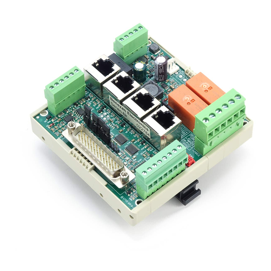
Brief product description
The breakout board allows the operation of up to four stepper motor or servo output stages at the parallel port of
a PC. For this purpose a control software like Beamicon2, Beamicon2-Basic (or e.g. Mach3, CNC-FRS,
WinPCNC, EMC or similar) is required (not included). The board can be adjusted to many different
configurations. Depending on the selected configuration, additional functions such as control of a frequency
converter or speed controller, reference switches, up to 2 relay outputs, an output for a holding brake and a
watchdog (so-called "charge pump") are available.
All signals of the PC port are buffered, so that a maximum of noise immunity is achieved. All machine-side
signals are designed for 24V level, ensuring robustness and compatibility with industrial sensors. Ready-made
connection cables for BEAST stepper motor power amplifiers, UHU-DC servo controllers and brushless servo
systems from Sanyo-Denki are available (not included), so that quick and error-free wiring is possible.
Attention, NEW: Supply voltage maximum 75V! 5V- and 12V-output loadable up to 0,5A
Alternative Version "NETBOB" with Network connection available instead of LPT port
software)
Nicolas Benezan, Stauffenbergstr. 26, 72108 Rottenburg
Phone: +49 (0)7457/946365 0 benezan-electronics.de
Mini Breakout Board
Interface board for
CNC control via LPT port
Installation manual
Version 8
Installation ManualBreakout Board
Breakout8-Installation_Englisch
(Vereinigte Staaten).docxdocx 22.09.2020
(only with Beamicon2
Page
Advertisement
Table of Contents
Troubleshooting

Related Manuals for Benezan Electronics Mini Breakout Board


Summary of Contents for Benezan Electronics Mini Breakout Board
- Page 1 Benezan Electronics Installation ManualBreakout Board Hard- and software development Mini Breakout Board Interface board for CNC control via LPT port Installation manual Version 8 Brief product description The breakout board allows the operation of up to four stepper motor or servo output stages at the parallel port of a PC.
-
Page 2: Safety Instructions
Benezan Electronics Installation ManualBreakout Board Hard- and software development Safety Instructions The Breakout Board may only be installed and put into operation by qualified personnel. Please read the operating instructions carefully and follow all instructions exactly. Improper installation or operation of the device can cause damage to the electronics or the machine and can result in dangers to the health of the operating personnel. - Page 3 Benezan Electronics Installation ManualBreakout Board Hard- and software development LPT port (SUBD25, left) Description Description 1 Spindle, relay1, PWM 14 Cooling, relay 2 2 Direction X 15 Reference switch 4th axis 3 Step X 16 Watchdog, current reduction 4 Direction Y...
- Page 4 Benezan Electronics Installation ManualBreakout Board Hard- and software development Power stage outputs (4 x RJ45, center) Attention! Pin 1 is down, pin 8 up Description Current reduction Signal ground Step Direction Status (0=ok, 1=error) Signal ground Relay outputs (6-pole terminal X4, bottom right)
-
Page 5: Functional Description
No current reduction is used (jumper open, DIP3 on BEAST off) Connection of UHU servo controllers It is recommended to use the UHU version from Benezan Electronics ( SMD-UHU ). The current reduction signal should be deactivated for this purpose, otherwise the controller will make an uncontrolled emergency stop. -
Page 6: Relay Outputs
Benezan Electronics Installation ManualBreakout Board Hard- and software development Relay outputs The relay outputs 1 and 2 can be used to switch 230V consumers such as spindle motor, coolant pump or chip extractor. The current consumption must not exceed 8A per relay, otherwise the load must be switched with an external contactor. -
Page 7: Holding Brake
Benezan Electronics Installation ManualBreakout Board Hard- and software development This circuit controls whether the control software outputs a regular signal of constant frequency (nominal 1 to 12kHz). If this signal is missing, the relay outputs and the step signals are blocked. A short interruption of the signal for a maximum of two periods (2ms), on the other hand, does not lead to a switch-off, because this could lead to creeping step losses. - Page 8 Benezan Electronics Installation ManualBreakout Board Hard- and software development Configuration The breakout board can be adapted to the different applications with jumpers. There are two fields with pin headers, one with 11 pins next to the SUBD25 connector and one with 5 pins to the right of the RJ45 sockets.
- Page 9 Benezan Electronics Installation ManualBreakout Board Hard- and software development Connection to USB-CNC The breakout board can also be connected to the USB CNC controller V5A with an additional adapter. For a correct function of the watchdog the jumpers "WDCF" on the USB-CNC board must be plugged in as follows: upper jumper on the left, lower jumper on the left.
-
Page 10: Technical Data
Benezan Electronics Installation ManualBreakout Board Hard- and software development Technical data Absolute limit values The following parameters must not be exceeded under any circumstances to prevent damage to the device: Parameters min. max. Unit Operating voltage Storage temperature °C Operating temperature °C... -
Page 11: Commissioning And Troubleshooting
Benezan Electronics Installation ManualBreakout Board Hard- and software development Commissioning and troubleshooting If you are using the interface board for the first time, please check the following points again before switching it Are all terminal blocks correctly aligned in the slots (X1 to X4)? ... -
Page 12: Troubleshooting
Benezan Electronics Installation ManualBreakout Board Hard- and software development Troubleshooting The following table gives an overview of the most common errors and the possible causes. Symptom Cause LED "Power" (green left) is not Power supply (ground at pin 4 of X1, +15 to +75V at pin 5 of X1, right) not connected or wrongly polarized.
Need help?
Do you have a question about the Mini Breakout Board and is the answer not in the manual?
Questions and answers