
Related Manuals for Omega UWTC-RPT1


Summary of Contents for Omega UWTC-RPT1
- Page 1 User’ s Gui d e Shop online at omega.com e-mail: info@omega.com For latest product manuals: www.omegamanual.info UWTC-RPT1 Long Range Wireless Repeater/Receiver System For UW Series Transmitters...
- Page 2 Fax: (203) 359-7700 e-mail: info@omega.com For Other Locations Visit omega.com/worldwide The information contained in this document is believed to be correct, but OMEGA accepts no liability for any errors it contains, and reserves the right to alter specifications without notice.
-
Page 3: Table Of Contents
UTWC-RPT1 - Long Range Wireless Repeater/Receiver System For UW Series Transmitters Table of Contents Section Page Section 1 Introduction ..................1-1 1.1 Precautions ....................1-1 1.2 Safety Warnings and IEC Symbols ............1-1 1.3 Product Labeling ..................1-2 1.3.1 Receiver Front Label UWTC-REC1-915 .......... 1-2 1.3.2 Repeater Front Label UWTC-REC1.......... - Page 4 UTWC-RPT1 - Long Range Wireless Repeater/Receiver System For UW Series Transmitters 7.5 Repeater Operation ................... 7-3 7.5.1 Indicator Lights ................. 7-3 7.6 Receiver Operations .................. 7-3 7.6.1 Indicator Lights ................. 7-3 7.7 Environment/Operating Conditions ............. 7-4 7.7.1 Environment ..................7-4 7.7.2 Operating Conditions ...............
- Page 5 Description Page Section 1 Introduction IEC Symbols ..................1-1 Receiver Front Label UWTC-REC1-915 .......... 1-2 Repeater Front Label UWTC-RPT1 ..........1-2 System Components ................1-3 Section 3 Software Welcome Screen .................. 3-1 Select Install Screen ................3-2 Confirm Installation Screen .............. 3-2 License Agreement Screen ..............
- Page 6 UTWC-RPT1 - Long Range Wireless Repeater/Receiver System For UW Series Transmitters NOTES:...
-
Page 7: Section 1 Introduction
Introduction Section 1 - Introduction Please read this manual completely before installing and operating your wireless repeater and receiver system. It’s important to read and follow all notes, cautions, warnings and safety precautions before operating this device. “Device” refers to your transmitter, repeater, or receiver unit. 1.1 Precautions •... -
Page 8: Product Labeling
Operation is subject to the following two conditions: 1) This device may not cause harmful interference; 2) This device must accept any interference received, including interference that may cause undesired operation. omega.com OMEGA ENGINEERING, INC. Stamford, CT 06907 5-12 Vdc Figure 1-3. Repeater Front Label UWTC-RPT1... -
Page 9: Statement On Fcc And Ce Marking
® regulations that apply. OMEGA is constantly pursuing certification of its products to the European New Approach Directives. OMEGA will add the CE mark to every appropriate device upon certification. For additional information see Section 10 - Approvals & Regulatory Compliance. -
Page 10: Section 2 Hardware
After examining and removing contents, save packing material and carton in the event reshipment is necessary. 2.2 Included Items The following items are supplied in the UWTC-RPT1 box: • 1 Wireless Repeater with two Antennas attached (UWTC-RPT1) • 1 UWTC-RPT Manual (M4938) •... -
Page 11: Section 3 Software
The following program files are included on the UWTC User Software CD supplied with your Receiver. These files can also be downloaded from the omega.com website should you misplace your CD. • UWTC Connector/Transmitter Setup Utility Program • UWTC TC-Central Measurement and Data Logging Program 3.2 Software Installation... - Page 12 From this screen you select the folder were you want the program files installed on your PC. The default setting will install the software under your “Program” folders in a new folder named “Omega” To continue with installing the program click the “Next >” button.
- Page 13 Software Figure 3-4. License Agreement Screen From this screen you must select “Agree” to continue installing your program. After making your selection click the “Next >” button. The setup wizard will now install the software. Figure 3-5. Installation Complete Screen Congratulations! You have just successfully installed the TC-Central Program on your PC.
-
Page 14: Usb Driver Installation
Software 3.3 USB Driver Installation To install the USB software drivers that are required for your UWTC system components to operate correctly follow these procedures. NOTE: You need to have the TC-Central User Software CD that was supplied with your receiver loaded into the CD drive on your PC. - Page 15 Software Figure 3-7. Install Software Automatically Wizard Screen Next, check the “Install the software automatically” button. Then click the “Next>” button to continue. Figure 3-8. Completing The Found New Hardware Wizard Screen This screen will be displayed to indicate that the software drivers have been installed.
-
Page 16: Uwtc Connector/Transmitter Setup Utility Program Uwtc Tc-Central Measurement And Recording Program
Software Section 3.4 UWTC Connector/Transmitter Setup Utility Program UWTC TC-Central Measurement and Recording Program For detailed information on setting up your connector/transmitter, as well as using the TC-Central Measurement and Recording Program, please refer to the manual for the connector/transmitter you are using in your long range wireless system. -
Page 17: Section 4 Receiver Setup
Operation is subject to the following two conditions: 1) This device may not cause harmful interference; 2) This device must accept any interference received, including interference that may cause undesired operation. OMEGA ENGINEERING, INC. omega.com Stamford, CT 06907 5-12 Vdc Figure 4-1. Receiver Setup - UWTC-REC1-915 4.1 Connecting Your Receiver To Your PC... -
Page 18: Configure Your Receiver (Uwtc-Rec1-915)
Receiver Setup Section 4.1.1 Configure Your Receiver (UWTC-REC1-915) To complete this procedure your UWTC-REC1-915 receiver must be connected to a USB port on your PC. Open TC-Central Software and select "Configure Receiver" from the TOOLS menu. RF Network Settings: RF Channel This setting determines the operating channel on which RF connections are made between the transmitter, repeater and receiver. -
Page 19: Section 5 Repeater Setup
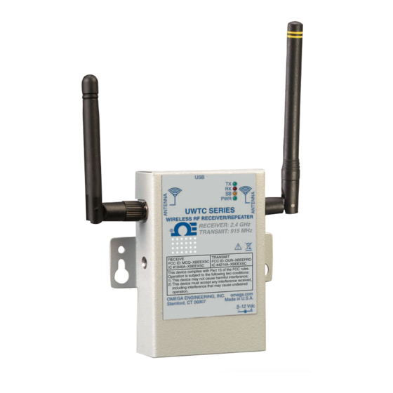
OMEGA ENGINEERING, INC. Stamford, CT 06907 5-12 Vdc Figure 5-1. Repeater Operation - Model UWTC-RPT1 (1) Receiving Antenna (2) USB Port (mini-B) (3) Indicator Lights (4) Transmitting Antenna (5) AC Power 5.1 Connecting Your Repeater to Your PC Connect the USB cable to your repeater unit and also to an available USB port on your PC. -
Page 20: Configure Your Repeater
Repeater Setup 5.1.1 Configure Your Repeater Start the End Device Configuration Wizard or select "Configure End Device" from the TOOLS menu in TC-Central. Figure 5-3. Setting Up the End Device If you have not already placed your End Device into SETUP mode you should do this now before continuing. - Page 21 Repeater Setup Figure 5-5. Read Settings Figure 5-6. Choose Options Choose the RF Network settings for the Repeater. Be sure to match "Receive" settings to that of the transmitter/connector, and the "Transmit" to that of the UWTC-REC1-915 receiver.
- Page 22 Repeater Setup Figure 5-7. Send Setting To End Device Congratulations! You have successfully programmed your repeater. After your unit has been programmed click the Finish button to close the utility program.
- Page 23 Repeater Setup NOTES:...
-
Page 24: Section 6 Repeater Mounting And Installation
Repeater Mounting and Installation Section 6 – Repeater Mounting and Installation 6.1 Mounting Mounting ears are built-in to your repeater enclosure The diagram below shows dimensions and mounting hole location. Rubber bumpers have also been supplied with your repeater should you wish to use the device on a desk or a work bench next to your PC. -
Page 25: Installation
Operation is subject to the following two conditions; 1) This device may not cause harmful interference; 2) This device must accept any interference received, including interference that may cause undesired operation. OMEGA ENGINEERING INC. omega.com Stamford, CT 06907 Made in U.S.A. 9-24 Vdc... -
Page 26: Antenna Connection
In the case that you want to improve range and signal strength for your repeater, you may replace your antenna with a high gain antenna (Omega Model No. RPT-HGA-915/868). This antenna is sold as an accessory. - Page 27 1) This device may not cause harmful interference; 2) This device must accept any interference received, including interference that may cause undesired operation. omega.com OMEGA ENGINEERING, INC. Stamford, CT 06907 5-12 Vdc Figure 6-4. Receiver Antenna Once you have replaced both antennas, the range increase is complete.
- Page 28 Repeater Mounting and Installation NOTES:...
-
Page 29: Section 7 System Operation
With the UWTC-RPT1 repeater in your UWTC series system, you are able to maintain a strong signal over a long distance. The UW series transmitter sends wireless transmissions to the UWTC-RPT1 repeater. -
Page 30: Connector/Transmitter Operation
System Operation 7.4 Connector/Transmitter Operation 7.4.1 Button Operation (1.) “PRESS ON/OFF” The “PRESS ON/OFF” button on the front of your connector/transmitter is used to turn your unit “ON” or “OFF” (2.) “PRESS SETUP” The “PRESS SETUP” button on the front of your connector/transmitter is only used during the setup and configuration of your unit. -
Page 31: Repeater Operation
System Operation PRESS SETUP ® PRESS ON/OFF LOW BATT UWTC UNIVERSAL WIRELESS THERMOCOUPLE CONNECTOR Figure 7-3. Transmit and Low Battery Lights 7.5 Repeater Operation 7.5.1 Indicator Lights (1) Transmit (TX) Green Indicator Light The top green indicator light marked “TX” on the front of the repeater will only blink when the repeater is connected to your PC and you initialize your measurement software. -
Page 32: Environment/Operating Conditions
7.7 Environment/Operating Conditions 7.7.1 Environment Omega’s UWTC or UWRTD series connector/transmitter, repeater, and receiver units have been designed to be fixed mounted and operated in a clean and dry indoor environment. Care should be taken to prevent the components of your wireless system from being exposed to moisture, toxic chemicals and extreme cold or hot temperature that are outside the specifications listed in this manual. -
Page 33: Determining And Maximizing Range
System Operation 7.8 Determining and Maximizing Range NOTE: The available maximum range specified for the wireless Series system in this manual is only achievable under optimum installation conditions. Mounting height, obstructions in your “Fresnel Zone” and ambient conditions can cause a decrease in signal strength resulting in a shorter range between your transmitter/connector and receiver unit. -
Page 34: Operation In Buildings
System Operation Maintain a line of sight (LOS) between antennas Maintaining a line of sight between your connector/transmitter and receiver unit will produce greatly improved signal strength over a system were the antennas in your system have obstacles blocking them. Maintain a constant ambient temperature environment Maintaining a constant ambient temperature environment is important to achieving maximum signal strength. -
Page 35: Antenna Basics
Operation is subject to the following two conditions: 1) This device may not cause harmful interference; TRANSMIT: 915 MHz 2) This device must accept any interference received, including interference that may cause undesired operation. OMEGA ENGINEERING, INC. omega.com Stamford, CT 06907 Made in U.S.A. RECEIVE TRANSMIT... -
Page 36: Vertical Antenna Placement
Operation is subject to the following two conditions; 1) This device may not cause harmful interference; 2) This device must accept any interference received, including interference that may cause undesired operation. OMEGA ENGINEERING INC. omega.com Stamford, CT 06907 Made in U.S.A. 9-24 Vdc... - Page 37 System Operation NOTES:...
- Page 38 UTWC-RPT1 - Long Range Wireless Repeater/Receiver System For UW Series Transmitters NOTES: 7-10...
-
Page 39: Section 8 Troubleshooting
System. If the problems and solutions outlined here do not solve your problem, please contact Omega’s customer service department. Contact information can be found in Section 2 of this manual or by visiting omega.com. 8.1 Connector/Transmitter Troubleshooting Problem Solution 1. -
Page 40: Section 8 Service And Calibration
If any of your wireless system components require service or calibration, please call our Customer Service Department at 1-800-622-2378 or 203-359-1660. They will assist you in arranging the return and service of your device. We can also be reached on the Internet at www.omega.com, e-mail: cservice@omega.com... -
Page 41: Section 10 Specifications
Specifications Section 10 – Specifications 10.1 Repeater Specifications Power: 5-12Vdc @ 500 mA (AC wall adapter included) Ambient Operating Conditions: 0 to 55°C (32 to 131°F), 90% RH non- condensing Wireless Communication 2.4 GHz Receiving Frequency: Transmitting Frequency: 915 MHz (USA/Canada), 868 MHz (Europe) RF Transmit Power: 100 mW (+20 dBm) Indoor/Urban Range:... -
Page 42: Section 11 Approvals, Regulatory Compliance, & Patent Notice
11.2 International Usage & CE Marking (Pending) The UWTC and UWRTD Series system components are CE marked and certified for use in several European countries. Please contact OMEGA for information on International Regulatory Compliance for each country. It is your (the user’s) responsibility to insure that these products are operated within the guidelines here in this manual and in conformance with all local or national regulations and laws. - Page 43 Department will issue an Authorized Return (AR) number immediately upon phone or written request. Upon examination by OMEGA, if the unit is found to be defective, it will be repaired or replaced at no charge. OMEGA’s WARRANTY does not apply to defects resulting from any action of the purchaser, including but not limited to mishandling, improper interfacing, operation outside of design limits, improper repair, or unauthorized modification.
- Page 44 Where Do I Find Everything I Need for Process Measurement and Control? OMEGA…Of Course! Shop online at omega.com TEMPERATURE M U Thermocouple, RTD & Thermistor Probes, Connectors, Panels & Assemblies M U Wire: Thermocouple, RTD & Thermistor M U Calibrators & Ice Point References M U Recorders, Controllers &...
Need help?
Do you have a question about the UWTC-RPT1 and is the answer not in the manual?
Questions and answers