
Related Manuals for Balluff BES M12EN-PFC40F-S04G-D11


Summary of Contents for Balluff BES M12EN-PFC40F-S04G-D11
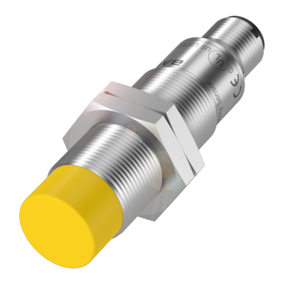
- Page 1 BES M12EN-PFC40F-S04G-D11 BES M18EN-PFC80F-S04G-D11 BES M18MN-PFC50B-S04G-D11 BES M30EN-PFC15F-S04G-D11 BES M30MN-PFC10B-S04G-D11 Inductive Safety Sensors User's Manual english...
- Page 2 Some of these trademarks may be registered trademarks of the respective owners. Balluff is not liable for any technical or printing errors, removal of the text contained herein or unintended damage resulting from use of the material.
-
Page 3: Table Of Contents
General Safety Notes Approved Use Non-approved Use Personnel Requirements Obligations of the Operating Company Installation Electrical Connection Operation as 4-conductor Operation as 3-conductor Operation Switching state of the outputs Response times LED display Technical Data Maintenance, Care, and Disposal Troubleshooting www.balluff.com... -
Page 4: About This User's Guide
Note In the interest of continual product improvements the technical data for this product and the contents of this user's guide are subject to change without notice. The latest status of this user's guide is available on Balluff website www.balluff.com. -
Page 5: Typographical Convention
► Action instruction 2 Action sequences are numbered in order: 1. Step 1 2. Step 2 3. Step 3 Symbols Note The symbol and the word Note indicate information which is helpful or important for use of the product. www.balluff.com... -
Page 6: Abbreviations
BES M…-D11 Inductive Safety Sensors Abbreviations Common Cause Failure Failure as a consequence of as common cause Diagnostic Coverage Diagnostic Coverage MTTF Mean Time To Dangerous Failure Mean Time To Dangerous Failure OSSD Output Signal Switch Device Output Signal Switching Device Probability of (dangerous) Failure per Hour (PFH Probability of (dangerous) Failure per Hour... - Page 7 The general warning symbol combined with the signal word WARNING indicates a risk which can result in serious injury or death. DANGER The general warning symbol combined with the signal word DANGER indicates a risk which can result directly in serious injury or death. www.balluff.com...
-
Page 8: About This Product
Scope of delivery The inductive safety sensor version BES0574, BES0575, BES0576, BES0578 and BES0579 detects metal without contact. Scope of delivery Order code BES M12EN-PFC40F-S04G-D11: 1 Safety sensor BES0574 2 Mounting nuts M12 1 Original user's guide BES M18EN-PFC80F-S04G-D11: 1 Safety sensor... -
Page 9: Function
BES M…-D11 Inductive Safety Sensors Note Should one of the components listed be missing or damaged, please contact one of the Balluff subsidiaries. Function BES0574: 1 Safety sensor LEDs 2 Close zone 3 Release zone 4 Assured turn-off distance s ar "0"... - Page 10 BES M…-D11 Inductive Safety Sensors BES0576: 1 Safety sensor LEDs 2 Close zone 3 Release zone 4 Assured turn-off distance s ar "1" "0" 5 Damping element Yellow signal LED: Switching state Green power LED: Operating voltage BES0578: 1 Safety sensor LEDs 2 Close zone 3 Release zone...
-
Page 11: Release Zone
0…3.1 mm 0…5.6 mm 0…3.5 mm 0…11.4 mm 0…7.4 mm steel 1.4301 (V2A) AIMg3G22 0…1.8 mm 0…3.2 mm 0…2 mm 0…6.8 mm 0…4.3 mm CuZn37 0…2 mm 0…3.2 mm 0…2 mm 0…7.2 mm 0…4.6 mm 0…1.2 mm 0…2.4 mm 0…1.5 mm 0…5.5 mm 0…3.3 mm www.balluff.com... -
Page 12: Relevant Standards
BES M…-D11 Inductive Safety Sensors 1) Typical values for damping with a reference target (according to EN 60947-5-2 at an ambient temperature of 20 °C): – BES0574: 12 x 12 x 1 mm and non-flush installation – BES0575: 24 x 24 x 1 mm and non-flush installation – BES0576: 18 x 18 x 1 mm and flush installation –... -
Page 13: General Safety Notes
For more information refer to see Section 4 Installation on page 17. The inductive safety sensor has been certified by TÜV NORD. Note The EU Declaration of Conformity as well as the certificates for EN/IEC 61508 and EN/ISO 13849-1 from TÜV NORD can be found at www.balluff.com. www.balluff.com... -
Page 14: Non-Approved Use
BES M…-D11 Inductive Safety Sensors Non-approved Use Warranty and liability claims against the manufacturer are rendered void by: – Unauthorized tampering – Improper use – Use, installation or handling contrary to the instructions provided in this User's Guide. – The sensor is not permitted to be used as a mechanical stop. –... - Page 15 Section 8 Maintenance, Care, and Disposal on page 30). Contact the manufacturer for any special ambient conditions. – Use only within the specified application description. – Safety requirements for the application – The safety requirements for the respective application must agree with the requirements laid out here. www.balluff.com...
- Page 16 BES M…-D11 Inductive Safety Sensors Observe the following conditions: ► Take measures which prevent metallic objects from unknowingly contacting the active surface. ► For interlocking devices together with guards observe DIN EN ISO 14119. ► Maintain specified application conditions (see Section 7 Technical Data on page 26). ►...
-
Page 17: Installation
► Protect the active surface of the sensor against falling metallic objects (e.g. by having the active surface pointing down). ► Otherwise use the sensor only after strict evaluation of the accident risk and documented risk assessment. www.balluff.com... - Page 18 BES M…-D11 Inductive Safety Sensors ► Secure the device against coming loose (observe tightening torque in the table). Order code Installation Tightening torque BES0574 Non-flush mount ≤ 7 Nm BES0575 Non-flush mount ≤ 25 Nm BES0576 Flush-mounted ≤ 25 Nm BES0578 Non-flush mount ≤ 50 Nm BES0579 Flush-mounted ≤ 50 Nm ►...
- Page 19 BES M…-D11 Inductive Safety Sensors BES0578: BES0579: Figure 3 Installation dimensions by type www.balluff.com...
-
Page 20: Electrical Connection
BES M…-D11 Inductive Safety Sensors Electrical Connection NOTICE Exceeding maximum voltage In case of a single fault, exceeding the maximum supply voltage of 40 V DC can result in destruction of the device and loss of the safety functionality. ► Ensure separation of the supply voltage and transformer. Connecting the safety sensor: 1. -
Page 21: Operation As 3-Conductor
The device performs self-tests for turn-off capability on A2. Operation as 3-conductor NOTICE Loss of the safety functionality When using an output other than A2 the safety functionality is completely lost. ► When operating in 3-conductor mode use only A2 as the output (OSSD). www.balluff.com... - Page 22 BES M…-D11 Inductive Safety Sensors NOTICE Function fault from cross-connections and short-circuits Inappropriate installation can cause cross-connections and short- circuits between the supply voltage and output A2. ► Install the devices only in suitable configurations according to this user's guide. Connections for 3-conductor operation: ►...
-
Page 23: Operation
A1 and A2 (OSSDs) are released (Logic "1"). Output specifications The output specifications are based on the specifications for the input per EN 61131-2 Type 1 or Type 2: Logic "1" ≥ 15 V 2…15 mA ≥ 11 V 15…30 mA Logic "0" ≤ 5 V Residual current 0.2 mA www.balluff.com... -
Page 24: Response Times
BES M…-D11 Inductive Safety Sensors Response times Description Type BES0574 BES0578 BES0575 BES0579 BES0576 Response time to a safety request ≤ 1 ms ≤ 10 ms (removing from the release zone) Response time when approaching ≤ 1 ms the release zone (release time) Risk time / error response time for ≤... -
Page 25: Led Display
Damping element within Both outputs the release zone released Signal Damping element within Output A2 is Power the close zone turned off 1) Sensor undamped 2) Sensor damped LED on LED off LED flashing (2 Hz) LED flashing rapidly (5 Hz) www.balluff.com... -
Page 26: Technical Data
BES M…-D11 Inductive Safety Sensors Technical Data BES0574 BES0575 BES0576 BES0578 BES0579 Product Features Plug connection Metal threads M12 × 1 M18 × 1 M18 × 1 M30 ×1.5 M30 ×1.5 Release zone 0.5…4 mm 1…8 mm 1…5 mm 1…15 mm 1…10 mm Non-flush Non-flush Flush- Non-flush Flush-... - Page 27 Response time Response time to ≤ 1 ms ≤ 1 ms ≤ 1 ms ≤ 10 ms ≤ 10 ms a safety request (removing from the release zone) Response ≤ 1 ms time when approaching the release zone (release time) Risk time (fault ≤ 20 ms ≤ 20 ms ≤ 20 ms ≤ 30 ms ≤ 30 ms response time) www.balluff.com...
- Page 28 BES M…-D11 Inductive Safety Sensors BES0574 BES0575 BES0576 BES0578 BES0579 Environmental conditions Operating Class C per EN 60654-1 Weather-protected conditions Ambient –25…70 °C, for service life ≤ 87,600 h temperature 10…40 °C, for service life ≤ 175,200 h Temperature 0.5 K/min change rate Max. permissible 5…95 %, short-time relative humidity 5…70 %, continuous Air pressure 80…106 kPa...
- Page 29 Unless otherwise indicated, all data in the entire temperature range are based on a reference target per IEC 60947-5-2 (FE360 = ST37K) 12 x 12 x 24 x 24 x 18 x 18 x 45 x 45 x 30 x 30 x 1 mm 1 mm 1 mm 1 mm 1 mm www.balluff.com...
-
Page 30: Maintenance, Care, And Disposal
BES M…-D11 Inductive Safety Sensors Maintenance, Care, and Disposal No special measures for maintenance and upkeep are necessary when operated properly. The device may be repaired only by the manufacturer. Dispose of the device in accordance with the prevailing national regulations for environmentally safe disposal. -
Page 31: Troubleshooting
No close zone Damping element shifts the If possible change the release zone directly up material, shape or size of to the sensor face due to the damping element (see its composition (material, Section 3.1 Approved Use shape, size). on page 13). www.balluff.com... - Page 32 Balluff GmbH Schurwaldstraße 9 73765 Neuhausen a.d.F. Germany Phone +49 7158 173-0 Fax +49 7158 5010 balluff@balluff.de www.balluff.com...
Need help?
Do you have a question about the BES M12EN-PFC40F-S04G-D11 and is the answer not in the manual?
Questions and answers