Table of Contents
Advertisement
Quick Links
Advertisement
Table of Contents

Related Manuals for IFM DTE830


Summary of Contents for IFM DTE830
- Page 1 Operating instructions RFID UHF reader DTE830 DTE930...
-
Page 2: Table Of Contents
RFID UHF reader Contents 1 Preliminary note � � � � � � � � � � � � � � � � � � � � � � � � � � � � � � � � � � � � � � � � � � � � � � � � � 3 1�1 Symbols used�... -
Page 3: Preliminary Note
Warning of damage to property 1.3 Copyright and trademarks © All rights reserved by ifm electronic gmbh� No part of these instructions may be reproduced and used without the consent of ifm electronic gmbh� All product names, pictures, companies or other brands used on our pages are the... -
Page 4: Safety Instructions
● Protect units and cables against damage� 3 Functions and features The multiprotocol-capable RFID reader DTE830 / DTE930 reads active and passive ID tags in different frequency ranges: ● Europe: 865 - 868 MHz ● USA: 902 - 928 MHz ●... -
Page 5: Radiated Electromagnetic Field Strength
The device complies with the requirements to CE� Brand name: ifm electronic DTE830 RFID UHF reader for Europe The device is designed for operation in accordance with EN 302208� When operating the device with connected antennas, observe the human exposure regulations to EN 50364�... -
Page 6: 4�1�2 Ised Canada Regulatory Information
34 centimetres between the radiator and your body� 4.1.4 C-Tick requirements The device complies with the requirements to C-Tick� Brand name: ifm electronic DTE930 RFID UHF reader for Australia 5 Items supplied ● Device ● Grounding material The device is supplied without installation and connection accessories�... -
Page 7: Installation
► Install the device via the mounting holes� ► Use strain reliefs for cables connected to the device� The device complies with the protection rating IP67 if unused connections are covered� The device is supplied without installation and connection accessories� Matching accessories at www�ifm�com... -
Page 8: 6�2 Eliminate Radio Disturbance
RFID UHF reader 6.2 Eliminate radio disturbance The device usually operates without any interference caused by radio communication, provided it is ● used as intended (→ 3 Functions and features), ● correctly installed (→ 6 Installation). The operation free of radio disturbance cannot be guaranteed for each application�... -
Page 9: Electrical Connection
RFID UHF reader 7 Electrical connection Observe the following instructions before electrical installation� ATTENTION! The device must be connected by a qualified electrician� Observe the electrical data in the data sheet� Device of protection class III (PC III). The electrical supply must only be made via PELV circuits� For cable lengths >... -
Page 10: 7�2 Power Supply
RFID UHF reader 7.2 Power supply The power supply is designed as a 4-pole M12 round connector with A-coding� Connection Original Scale Drawing (MTD) + 24 V DC Only use power supplies with limited power for operation: The power supply must be below 100 W on the secondary side�... -
Page 11: 7�4 Digital Inputs And Outputs
RFID UHF reader 7.4 Digital inputs and outputs The digital inputs and outputs are designed as 12-pole M12 socket with A coding� Connection Description OUT_CMN common switching output OUTPUT 1 switching output 1 INPUT 3 switching input 3 INP_CMN common switching input INPUT 1 switching input 1 GND_extern... -
Page 12: 7�4�2 Digital Outputs
RFID UHF reader Input 1 Input 1 Input 2 Input 2 Input 3 Input 3 Input 4 Input 4 INP_CMN Fig� 6: Circuitry of the inputs not electrically isolated 7.4.2 Digital outputs The outputs are electrically isolated from the operating voltage of the device and have a common pole (switching output CMN). -
Page 13: 7�5 Antenna Connection
7.5 Antenna connection For connection with the RFID antennas, the device has 4 antenna connections which are designed as Reverse TNC� Unsuitable cables decrease the power of the device� For connection of antennas, only use approved cables� Matching accessories at www�ifm�com... -
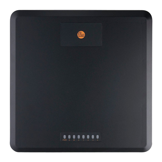
Page 14: Operating And Display Elements
RFID UHF reader 8 Operating and display elements 1: operating status 2: no function 3: freely programmable Fig� 9: Display elements on the front of the device 8.1 LED PWR The device displays the operating states via a 2-colour LED� Meaning Status yellow... -
Page 15: Configuration
The devices are controlled and evaluated by means of the ● ReaderStart software, ● supplied DLL or ● proprietary reader protocol from ifm electronic� The GS1 EPCGlobal Standard describes the interface between device and and ID tag� Further information at: www�epcglobalinc�org The parameters for the configuration of the device are described in the software manual�...
Need help?
Do you have a question about the DTE830 and is the answer not in the manual?
Questions and answers