Table of Contents
Advertisement
Advertisement
Table of Contents

Related Manuals for IBA ibaRackline

Summary of Contents for IBA ibaRackline
- Page 1 Industrial Computer Manual Issue 1.16...
- Page 2 Required corrections are contained in the following regulations or can be downloaded on the Internet. The current version is available for download on our web site http://www.iba-ag.com. Windows® is a label and registered trademark of the Microsoft Corporation. Other product and company names mentioned in this manual can be labels or registered trademarks of the corresponding owners.
-
Page 3: Table Of Contents
Power supply slide-in module for replacement of redundant power supply unit ..................28 8.4.3 Replacing the complete redundant power supply unit ........28 Restoring of a RAID system during operation ..........31 Installing operating system and iba software ..........36 Installation ....................36 Issue 1.16... - Page 4 9.2.4 Partitioning ....................37 9.2.5 Completing installation ................39 Windows Updates ..................40 Antivirus Software ..................40 Installing iba software .................. 40 Device dimensions ..................41 Technical data ....................42 11.1 Main data ....................42 11.2 Electronic components and interfaces ............43 11.3...
-
Page 5: About This Manual
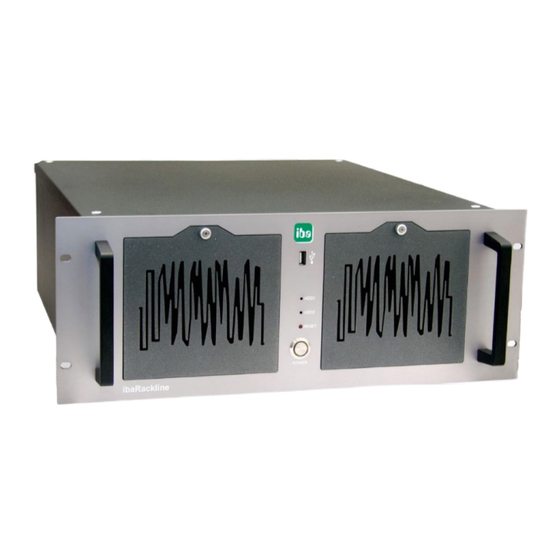
Manual About this manual This manual describes operation of the industrial PC ibaRackline. Target group This manual addresses in particular the qualified professionals who are familiar with han- dling electrical and electronic modules as well as communication and measurement tech- nology. -
Page 6: Symbols Used
- By an electric shock! - Due to the improper handling of iba software products which are coupled to input and output procedures with control function! If you do not observe the safety instructions regarding the process and the system or... -
Page 7: Scope Of Delivery
iba software, optional order Hardware driver (motherboard, graphic card) 1 iba software license key (dongle), optional with iba software product and installed inside of the device on request of the client Serial number (iba-S/N) -
Page 8: Versions
Manual ibaRackline Versions ibaRackline (Xeon E, Windows 10 IoT Enterprise Long-Term-Servicing Version) with one hard disk, can be upgraded with up to 7 further hard disks Enhancement options: RAID 1 system with 2 hard disks, 1 redundant power supply unit (The data are mirrored.) -
Page 9: Safety Instructions
The device may be used only for the following applications: Machine test and commissioning of industrial systems Measurement data logging and analysis Applications of iba software products (ibaPDA, ibaLogic etc.) Proper installation site The device can be installed only according to manufacturer's specifications: ... -
Page 10: Description
Optical drive with integrated writing function Plug-in slots for hard disks Note On delivery of the device the iba software license key is in the documentation or on client's request plugged-in in the device. Display elements The display consists of 2 LEDs:... -
Page 11: Rear View
5.2.1 Standard system version ibaRackline Power supply with switch and panel plug for non-heating appliances Slots X20 to X26 (iba-cards for rackline slot, e.g. output connection for ibaFOB-i cards) Connections for external devices (keyboard, mouse, network etc.) Hard disk controller... -
Page 12: Internal View
5x PCI Express slots, 1x PCI slot Hard disk controller Slots for iba-cards for rackline slot or additional fan (as option) Power supply unit (for RAID systems redundant) Drive frame Fan ( Ø 12 cm), mounting angle for redundant power supply unit... -
Page 13: Error Monitoring
The cards can be ordered separately. If one of the cards is ordered with ibaRackline, it is installed by default in slot X20. If you want to install the card later on, refer to chapter 7.4. -
Page 14: Ibaout-State
The behavior of ibaOut-State is identical with the previous models with a relay output, if pin 5 and 6 are used. The relay contact of the previous ibaRackline models is closed when an error occurs, without differentiating between overtemperature or a power supply error. -
Page 15: Default Installation Position For Cards
Manual Default installation position for cards On delivery, the data acquisition cards and other additional cards are installed by default in the slots as described below. Installation slots for data acquisition cards (X3 – X7) The cards are installed starting with slot X7 to slot X3 (X7 corresponds to the first card, card no. -
Page 16: Installation, Connection And First Switching On
(fiber optic and copper data cable) are plugged. The device is delivered in a pre-installed and configured state. You can find the parameters of the operating system and iba software in the corresponding manuals or in the online help. -
Page 17: Installation Of Measuring Or Additional Boards
Manual Installation of measuring or additional boards Safety instructions and notes Electric Shock! Before opening shut down the device! After that disconnect it from the mains and pull out the mains plug from the socket equipped with earthing contact! -
Page 18: Opening The Device
Manual ibaRackline Opening the device 1. Turn the screws located on the upper side of the cover a quarter of a turn counter- clockwise. 2. Lift the housing cover. Issue 1.16... -
Page 19: Installing Ibaout-Temp/Ibaout-State
Manual Installing ibaOut-Temp/ibaOut-State The temperature and the status of the power supply unit can be monitored with the slot cards ibaOut-Temp and ibaOut-State, see also chapter 5.4. The installation procedure is identical for both cards. The following description is based on the example of ibaOut-Temp. - Page 20 Manual ibaRackline Electrostatic discharge! Touch the components only in electrostatically discharged state! Hold the card cautiously at the edges and at the slot bracket. 4. Insert the card in the respective slot. The bar at the bottom is used to fix the card.
- Page 21 Manual 6. Connect the cables as follows: (1): Connection of redundant power supply unit: If a redundant power supply unit is to be monitored, connect the twisted cable (black/red) of the power supply unit (1 – picture above) to the 2-pin connector (1 – picture below) of the card. This connec- tion is not necessary, when a standard power supply unit is used.
-
Page 22: Installing Additional Fan
Manual ibaRackline 7. Properly installed card: 8. Fix the cable with a cable tie and close the housing cover. Installing additional fan If needed, it is possible to install one or two additional fans in the slots X21 to X26. Each fan requires the space of 3 slots. - Page 23 Manual 2. Loosen the screws in the openings above the slots. 3. Insert the fan module on the inner side on the rear cover, for this purpose push the bent slot bracket onto the rear cover. Fasten the fan with the screws removed be- fore.
- Page 24 Manual ibaRackline 4. Insert the plug of the fan power supply cable into the appropriate plugs on the moth- erboard, see picture below. 5. The guide pins on the plug ensure a proper position of the connection. 6. Close the housing cover.
-
Page 25: Maintenance Work
1. Loosen the fastening screw which is used to fix the grid and open the grid. 2. Take the dust filter out of the grid. 3. Clean the dust filter or insert a new one (iba filter mat: Order number 43.000360). 4. Close the grid again and fasten the screw. -
Page 26: Cleaning And Replacing The Fan
Manual ibaRackline Cleaning and replacing the fan Depending on the installation site it is necessary to clean or replace the fan. First, remove the grid as described above and proceed as follows: 1. Loosen all 4 fastening screws which are used to fix the fan. -
Page 27: Replacing The Standard Atx Power Supply Unit
Manual 8.4.1 Replacing the standard ATX power supply unit 1. Loosen the 4 fastening screws on the backside, which are used to fix the power supply unit at the housing. 2. Loosen 2 screws each on the left and the right side, which are used to fix the bar (1) and remove the bar. -
Page 28: Power Supply Slide-In Module For Replacement Of Redundant Power Supply Unit
2. Pull out the power supply slide-in module. Replace the power supply slide-in module with the module of the same type (availa- ble at iba). 8.4.3 Replacing the complete redundant power supply unit 1. First remove the power supply slide-in module, as described above. - Page 29 Manual 3. Loosen both screws inside, which are used to fix the power supply unit inside the housing. 4. Loosen 2 screws each on the left and the right side, which are used to fix the bar (1) and remove the bar.
- Page 30 Manual ibaRackline 8. In order to install a new power supply unit, proceed in reversed order. Issue 1.16...
-
Page 31: Restoring Of A Raid System During Operation
Manual Restoring of a RAID system during operation Only qualified professionals are allowed to replace a hard disk unit during operation! Electrostatic discharge! Touch the components only in electrostatically discharged state! Important Note The RAID system is not automatically restored after having changed the hard disk. Use the program "maxView Storage Manager". - Page 32 Manual ibaRackline 3. A click on <Login> opens the program window of the manager. The defective hard disk is not indicated. 4. Mark the hard disk, which is available (“Device 1” in the example above) and click on the „Locate“ icon in the “Physical device”...
- Page 33 Manual 6. The new hard disk is indicated in the „maxView Storage Manager“. But the hard disk has not been registered in the system. 7. Mark the new hard disk („Device 2“ in the example above) and click on the „Initialize“...
- Page 34 Manual ibaRackline 10. Confirm the following overview with <Finish>. 11. The following message appears when the operation was successful. Otherwise an error message appears. Issue 1.16...
- Page 35 Manual 12. The progress of the rebuild process is displayed under “Tasks”. 13. As soon as the hard disk has been successfully registered in the system, the pro- gram can be closed. Issue 1.16...
-
Page 36: Installing Operating System And Iba Software
If you modify the device components, it may not be possible to install it with the Recov- ery DVD. Installing Windows from the recovery medium Important note The Windows license is bound to the computer where iba software is installed. The li- cense must not be used on another computer. 9.2.1 General ... -
Page 37: Select The Language
Manual Note The recovery process takes approx. 50 minutes. It is possible that only a black or green screen is visible during the process. 9.2.2 Select the language When the installation has started, you can select the system language to be installed. - Page 38 Manual ibaRackline Substitute the operating system on a drive already used (substitute Windows 10 Enterprise with Windows Server or vice versa) Possibility 1: New drive You use a new drive and want to use it completely as system drive.
-
Page 39: Completing Installation
Manual Possibility 3: Restoring or replacing the operating system The drive is already in use and you want to install the operating system. 1. Mark the system partition (usually 500 MB in size) 2. Click <Format> 3. Confirm with <OK>... -
Page 40: Windows Updates
Windows Updates The automatic search for updates is deactivated by default on iba systems, as iba does not know which Windows update policies apply in your company. Please adjust the settings according to the update policies in your company. Consult your IT department if necessary. -
Page 41: Device Dimensions
Manual Device dimensions (Dimensions given in mm) Issue 1.16... -
Page 42: Technical Data
Max. DC 400 W ibaRackline RAID 1 / 6 AC 100 V to 240 V; 8 A/4 A 47 Hz to 63 Hz Power output ibaRackline RAID 1 / 6 1 x redundant 500 W Mechanical data Installation height (HU - Height Unit) -
Page 43: Electronic Components And Interfaces
32 GB DDR4 Microsemi Adaptec SmartRAID 3102-8i PCI Express x16: SAS controller PCI Express, free 5x for iba measuring cards PCI, free 1x M-Key (2242/2260/2280), PCI-e 4 1x A-Key (2230), supports WiFi module USB 2.0 2x frontside (1x dongle, 1x frontside) USB 3.0... -
Page 44: Products
HD 600GB to 1200GB Upgrade SAS 43.000420 HD 600GB to 1800GB Upgrade SAS 43.000421 HD 600GB to 2400GB Upgrade SAS 43.000422 Upgrade ibaRackline-PC CAM with NVME-SSD for OS installation 43.001002 Accessories HD 600 GB SAS 43.000326 HD 1200 GB SAS 43.000329... -
Page 45: Support And Contact
Mailing address iba AG Postbox 1828 D-90708 Fuerth Germany Delivery address iba AG Gebhardtstrasse 10 DE-90762 Fuerth Germany Regional and Worldwide For contact data of your regional iba office or representative please refer to our web site www.iba-ag.com. Issue 1.16...
Need help?
Do you have a question about the ibaRackline and is the answer not in the manual?
Questions and answers