Table of Contents
Advertisement
Quick Links
Advertisement
Table of Contents

Related Manuals for Ross Abekas Mira


Summary of Contents for Ross Abekas Mira
- Page 1 Mira/Mira+ User Manual...
- Page 2 Ross has become well known for the Ross Video Code of Ethics. It guides our interactions and empowers our employees. I hope you enjoy reading it below. If anything at all with your Ross experience does not live up to your expectations be sure to reach out to us at solutions@rossvideo.com.
- Page 3 Ross Video. While every precaution has been taken in the preparation of this document, Ross Video assumes no responsibility for errors or omissions. Neither is any liability assumed for damages resulting from the use of the information contained herein.
- Page 4 Changes or modifications to this product not authorized by Ross Video Limited could void the FCC Compliance and ® negate authority to operate the product. This product was tested for FCC compliance under conditions that included the use of Ross ® Abekas ®...
- Page 5 Important: This is a Class A product. In domestic environments, this product may cause radio interference, in which case the user may have to take adequate measures. Safety and First Aid Ross ® Abekas ® equipment is designed to the highest standards of quality and reliability. However, no matter how these systems are designed, operators and maintenance personnel can be exposed to electrical shock hazard when protective covers are removed for maintenance or the installation of options.
- Page 6 Technical Support At Ross Video, we take pride in the quality of our products, but if a problem does occur, help is as close as the nearest telephone. Our 24-Hour Hot Line service ensures you have access to technical expertise around the clock. After-sales service and technical support are provided directly by Ross Video personnel.
-
Page 7: Table Of Contents
Contents Getting Started..............................11 Power On/Off..........................................11 Windows ® Login..........................................11 Software............................................11 Server Configuration............................12 Channel Setup..........................................12 To Configure the Hardware Channels................................14 Video Formats..........................................15 UHDTV1 Support......................................15 To Configure the Video Format..................................15 Video Router Setup........................................16 To Connect to a Video Router..................................17 Audio Setup...........................................17 To Configure the Audio Setup.................................. - Page 8 To Set the Initial Clip Name Options................................43 To Set the Clip Name Options..................................44 User Setup Files........................................... 44 To Save a User Setup File................................... 44 To Load a User Setup File................................... 44 To Name a Camera Input......................................45 Import................................46 Supported Media Files for Hardware Import................................46 Supported Transcode Import......................................
- Page 9 Softkey Buttons and Shift..................................... 90 T-Bar Area........................................91 Clip Control Area......................................91 Navigate Area........................................92 Live EE Area......................................... 92 Play List Area........................................ 93 Output Control Area...................................... 93 Rotary Dial Area......................................94 Play Back Area......................................94 Replay Window..........................................95 Playout Channels......................................96 Camera Inputs....................................... 96 Lists and Menu......................................96 Softkeys.........................................
- Page 10 DashBoard...........................................129 Clip ID Support........................................... 129 Sony ® MVS Series Switcher.......................................129 Maintenance..............................130 Media Drives..........................................130 Disk Space........................................130 Troubleshooting.............................131 Specifications..............................133 Resources........................................... 133 Operating Temperature....................................... 133 Ports................................134 Serial (RS422) Port........................................134 LTC Port............................................134 AES Audio Port...........................................134 Index..........................136 x • Contents — Mira/Mira+ User Manual...
-
Page 11: Getting Started
Getting Started The server consists of a 3RU computer with advanced video processing, storage, and streaming capabilities. The server runs a standard Microsoft Windows operating system with the pre-installed Abekas software applications for ® ® ® interacting with the video processing hardware. Power On/Off The system powers on with the single power button located at the front of the chassis. -
Page 12: Server Configuration
Server Configuration The Mira Config application allows you to configure various aspects of the hardware in your server. This includes video input and output, audio, timecode, compression and serial communications. The number of channels and inputs and outputs you have depend on the hardware installed in your server. Important: Not all settings are available on all servers or require a option to be purchased or installed. - Page 13 Mode Description ISO7 Seven (7) 2D cameras are recorded to the same clip ID on channels A-G. Channel H is the replay channel. This configuration requires all eight (8) channels. ISO8 Eight (8) 2D cameras are recorded to the same clip ID on channels A-H. There are no replay channels.
-
Page 14: To Configure The Hardware Channels
Mode Description SSM-3X ISO3 Two (2) 3-times slow motion channel transports with two (2) video links for each channel transport and two (2) replay channels. 2X Super Slow Motion Camera One (1) 2-times slow motion channel transport. 3X Super Slow Motion Camera One (1) 3-times slow motion channel transport. 4X Super Slow Motion Camera One (1) 4-times slow motion channel transport. -
Page 15: Video Formats
Video Formats When working in 3G video formats, or outputting for UHDTV1, the available formats and number of channels depends on the hardware you have installed in your server. JPEG 2000 AVC-Intra DVCPRO HD 1080i 4/8* 4/8/12* 4/8* 1080p Not Supported 4/8/12* Not Supported 3G Level A... -
Page 16: Video Router Setup
2. Click the Video tab. 3. In the Video Reference Frequency area, select the frequency you want the server to operate in. 4. In the Video Resolution area, select the video resolution you want the server to operate in. 5. In the Video Reference Source area, select the type of input reference signal that the server is using. This is the video signal that is connected to the Analog REF IN BNC on the back of the server. -
Page 17: To Connect To A Video Router
To Connect to a Video Router You can change which destinations are coming into the server from the router, as well as which sources on the router are routed to those destinations. 1. Launch the Mira Config application. You may be prompted to allow the program to make changes on the computer, click Yes. 2. -
Page 18: Audio Router Setup
2. Click the Audio tab. 3. In the Audio Tracks area, select the number of audio tracks to record. • 2 track audio — record two tracks of audio. • 4 track audio — record four tracks of audio • 8 track audio — record eight tracks of audio. This option is not available when the server is operating in an SD video format(525/480i or 625/576i). -
Page 19: To Configure The Audio Router
Server TASCAM TASCAM AES-59 AES-59 To Configure the Audio Router The Audio Input Router tab allows you to set the audio tracks that get recorded into clips stored on the server and the Audio Output Router tab allows you to set which audio is played from clips stored on the server. 1. - Page 20 3. Click the Audio Input Router tab. 4. Click on the tab for the channel transport that you want to route audio tracks to. 5. In the ChX Recorder Track 1 row, select the source channel input (ChX Input) and the audio track (Track #) from the input that you want to record on track 1 of the clip.
-
Page 21: Timecode Setup
9. In the ChX Audio Output Track 1 row, select the source channel player (ChX Player) and the audio track (Track #) from the player that you want to route to track 1 of the output video stream. 10. Repeat this step for all of the remaining output tracks and channel outputs. Tip: Click NORMANIZE ALL ChX Output Routes to reset all the player audio track to their default output track assignment. - Page 22 2. Click the Timecode tab. 3. In the Timecode Input Source area, select the timecode source for each channel. • Time of Day LTC In — the LTC signal coming into the server. • ATC In — the embedded digital timecode in the video source. 4.
-
Page 23: Compression Setup
7. Click Apply. Compression Setup Compression is applied to all new clips recorded on the server and is used to set the desired bit rate. The lower the bit rate, the lower the picture quality but the longer the recording time (smaller file). The higher the bit rate, the higher the picture quality but the longer the recording time (larger file). -
Page 24: Channel Label Setup
Channel Label Setup You can assign a custom name to each channel transport to help identify the server it is on or what it is used for. Channel transport labels are shown at the far right of each channel transport in Mira Explorer and on each box in the HD-SDI Quad Viewer output. -
Page 25: Count Down Display
• Channel, audio meters, and channel status are shown along the top of each box. • Clip name and timecode are shown along the bottom of each box. Count Down Display The Quad Viewer shows the program output for the Live EE, Playback, or Playlist AIR, depending how the server is configured. -
Page 26: Tsl Tally Setup
2. Click the Quad Viewer tab. 3. In the Output Display area, select whether the Quad Viewer (Quad Split Display) or Count Down (Count Down Display) are sent out the Quad Viewer output. 4. In the Clip Information Overlay area, adjust the opacity of the clip information text and background of the text. These overlays are shown in the corners of each Quad Viewer box. -
Page 27: To Configure The Tsl Tally Input
To Configure the TSL Tally Input Tally information sent to the server over ethernet using the TSL protocol is used to show red and green tallies (as well as gray and amber) on the channel labels. You will need the IP address and port of the device sending the tally information, as well as the screen mapping. -
Page 28: Replay Setup
Replay Setup To operate the server as a replay server you must configure channels in a replay (ISO) mode, connect a Control Surface, and open a replay event. Depending on the replay (ISO) mode you have selected, and the number of channels in your server, you can run both server and replay operations at the same time. - Page 29 Note: You must connect the Control Surface to the server before you try to configure the server. The server will detect the Control Surface and allow you to assign channels to them. 1. Launch the Mira Config application. You may be prompted to allow the program to make changes on the computer, click Yes. 2.
-
Page 30: User Setup
User Setup The user setup, or personality settings, allow you to customize the replay function to the activity or sport your are recording and your own personal preferences. To Set the Audio Tracks for the Headphones Assign an audio track to the left and right speakers on the headphone jack on the Control Surface, and set the volume. 1. -
Page 31: To Set The Pre-Roll Time
1. Press MARK + SCROLL. The User Setup menu opens. 2. Use the up and down arrows, or the rotary dial, to select PLAYLIST Auto-Fill based on Clip Name. 3. Press TOGGLE (4) to toggle this feature on or off. 4. -
Page 32: To Set The Default Fast Forward And Rewind Speeds
2. Use the up and down arrows, or the rotary dial, to select AUTO JOG for Rotary Dial. 3. Press TOGGLE (4) to toggle this feature on or off. 4. Press MARK + SCROLL again to close the menu. To Set the Default Fast Forward and Rewind Speeds Set the default speed that the fast forward and rewind functions operate at. -
Page 33: To Set The Max Cruise Speed
1. Press MARK + SCROLL. The User Setup menu opens. 2. Use the up and down arrows, or the rotary dial, to select FAST JOG Maximum Speed. 3. Use the keyboard to enter the multiplier you want to use (1X is real-time). 4. -
Page 34: To Set The Max T-Bar Speed (Var 2)
To Set the Max T-Bar Speed (VAR 2) Set the maximum speed video will move when the T-bar is in the maximum speed position (top) and the VAR 2 mode is active. 1. Press MARK + SCROLL. The User Setup menu opens. 2. -
Page 35: To Set The Min T-Bar Speed (Var 3)
1. Press MARK + SCROLL. The User Setup menu opens. 2. Use the up and down arrows, or the rotary dial, to select T-BAR VAR-3 MAX Speed. 3. Use the keyboard to enter the multiplier you want to use (1X is real-time). 4. -
Page 36: To Set The Auto-Mark Out-Point Offset
3. Use the keyboard to enter the amount of time (minutes:seconds:frames) you want to offset from the POI time. 4. Press MARK + SCROLL again to close the menu. To Set the Auto-mark Out-point Offset Set the timecode that is added to the point of interest (POI) timecode when saving a clip that have no out-point. Tip: The auto-mark out-point is used when there is no out-point defined and GOTO OUT is pressed. -
Page 37: To Set The Duration Of A Mix Transition
1. Press MARK + SCROLL. The User Setup menu opens. 2. Use the up and down arrows, or the rotary dial, to select 2-Replay Channel TRANSITION. 3. Select the type of transition you want to use to transition between the two channels. •... -
Page 38: To Set Whether Gang Mode Is Deselected If A Playout Channel Is Selected
To Set Whether Gang Mode is Deselected if a Playout Channel is Selected Set whether GANG is automatically deselected for Output Control when any of the playout channels (P1,P2,P3,P4) are selected. 1. Press MARK + SCROLL. The User Setup menu opens. 2. -
Page 39: To Set The Preferred Play List
4. Repeat these steps for the remaining playout channels. 5. Press MARK + SCROLL again to close the menu. To Set the Preferred Play List Set the preferred Play List for each playout channel when a Replay Event is launched. 1. -
Page 40: To Set Whether Play List Uses Pgm/Pvw
1. Press MARK + SCROLL. The User Setup menu opens. 2. Use the up and down arrows, or the rotary dial, to select Obey clip OUT point in CP Mode. 3. Press TOGGLE (4) to toggle this feature on or off. 4. -
Page 41: To Set The Amount Inactive Lists Are Dimmed
4. Press MARK + SCROLL again to close the menu. To Set the Amount Inactive Lists are Dimmed Set the amount the Clip Register or Play List are dimmed when not active. This helps to quickly focus on the list that is currently active. -
Page 42: To Set Playout Channel Color
1. Press MARK + SCROLL. The User Setup menu opens. 2. Use the up and down arrows, or the rotary dial, to select Light contrast. 3. Use the keyboard to enter the amount of contrast (0-900) you want to apply to the buttons on the Control Surface. 4. -
Page 43: To Set The Source Of The Name That Is Applied To New Clips
4. Press MARK + SCROLL again to close the menu. To Set the Source of the Name that is Applied to New Clips Set the source of the name that is applied to all camera angles when SAVE is pressed. 1. -
Page 44: To Set The Clip Name Options
To Set the Clip Name Options Set the name you would like to be able to assign to new clips from the Control Surface. When you press the corresponding softkey the name is applied to the clip after the prefix you added with the 8 or 9 softkey. Tip: You can also set the clip names from the Replay Event Setup menu (Press MARK + SCROLL >... -
Page 45: To Name A Camera Input
1. Press MARK + SCROLL > User Setup Files (5). 2. Select the drive where the file is stored. Note: If the file is stored on a USB drive, you must install the USB drive into the USB port on the front of the Control Surface. •... -
Page 46: Import
Import The Mira Import file import utility converts all imported media files to the current video output format that the server is operating in. For example, if the server is currently operating in the 1080i 59.94Hz video format, then all imported media files are converted to 1080i 59.94Hz video format. -
Page 47: Supported Transcode Import
File Type Codec Plug-in Calibrated{Q} XD Decode + MXF Import Bundle #1 (DV50) DVCPRO 50 Calibrated{Q} DV100 Decode + MXF Import Bundle #2 (DV25) DVCPRO Calibrated{Q} MXF Import (DV50) DVCPRO 50 Calibrated{Q} MXF Import Calibrated{Q} DV50 Decode (DV100) DVCPRO HD Calibrated{Q} DV100 Decode + MXF Import Bundle #2 Apple XDCam-HD... - Page 48 Video+Audio and Video Only Media Files Legend Codec Codec Description .DVI.. 012v Uncompressed 4:2:2 10-bit .DV.L. 4X Technologies Movie .DVI.S 8bps QuickTime 8BPS video ® .DV..S aasc Autodesk ® .DVIL. Apple Intermediate Codec ® EDVI.S alias_pix Alias/Wavefront PIX image EDVIL. AMV Video .DV.L.
- Page 49 Legend Codec Codec Description .DV..S cscd CamStudio (decoders: camstudio) ™ .DVIL. cyuv Creative YUV (CYUV) .DVILS Microsoft DirectDraw Surface image decoder ® .DV.L. DreamForge Chronomaster DFA EDV.LS dirac Dirac (encoders: vc2) ® EDVIL. dnxhd Avid VC3/DNxHD ® EDVI.S SMPTE DPX (Digital Picture Exchange) image ®...
- Page 50 Legend Codec Codec Description EDVI.S huffyuv Huffyuv .DV.L. idcin ZeniMax QUAKE II CIN video (decoders: idcinvideo) ® ® ® .DVI.. iCEDraw text .DV.L. iff_ilbm IFF ACBM / ANIM / EDEP / ILBM / PBM / RGB8 / RGBN (decoders: iff) .DV.L.
- Page 51 Legend Codec Codec Description .DV.L. mts2 Microsoft Expression Encoder Screen ® .DVIL. mvc1 Silicon Graphics Motion Video Compressor 1 ® .DVIL. mvc2 Silicon Graphics Motion Video Compressor 2 ® .DV.L. mxpeg MOBOTIX MxPEG video ® .DV.L. Nupplevideo/RTJPEG .DV.L. paf_video Amazing Studio Packed Animation File (PAF) Video EDVI.S PAM (Portable AnyMap) image EDVI.S...
- Page 52 Legend Codec Codec Description .DV... smvjpeg SigmaTel Motion Video EDV.LS snow Snow .DVIL. sp5x Sunplus JPEG (SP5X) EDVI.S sunrast Oracle Rasterfile image ® ® EDV.L. svq1 Sorenson Media Vector Quantizer 1 / Sorenson Video 1 / SVQ1 ® ® .DV.L. svq3 Sorenson Media Vector Quantizer 3 / Sorenson Video...
- Page 53 Legend Codec Codec Description .DV..S vmnc VMware Screen Codec / VMware Video ® ® .DV.L. On2 VP3 .DV.L. On2 VP5 .DV.L. On2 VP6 .DV.L. vp6a On2 VP6 (Flash version, with alpha channel) ® .DV.L. vp6f On2 VP6 (Flash version) ® .DV.L.
- Page 54 Legend Codec Codec Description EDA.L. ATSC A/52A (AC-3) (decoders: ac3 ac3_fixed) (encoders: ac3 ac3_fixed) .DA.L. adpcm_4xm ADPCM 4X Movie EDA.L. adpcm_adx SEGA CRI ADX ADPCM ® .DA.L. adpcm_afc ADPCM Nintendo Gamecube ® ® .DA.L. adpcm_aica ADPCM Yamaha AICA ® .DA.L. adpcm_ct ADPCM Creative Technology .DA.L.
- Page 55 Legend Codec Codec Description .DA.L. adpcm_thp ADPCM Nintendo ® .DA.L. adpcm_thp_le ADPCM Nintendo THP (Little-Endian) ® .DA.L. adpcm_vima LucasArts VIMA audio ® .DA.L. adpcm_xa ADPCM CDROM XA EDA.L. adpcm_yamaha ADPCM Yamaha ® EDA..S alac ALAC (Apple Lossless Audio Codec) ® .DA.L.
- Page 56 Legend Codec Codec Description .DA.L. interplayacm Interplay ® .DA.L. mace3 MACE (Macintosh Audio Compression/Expansion) 3:1 ® .DA.L. mace6 MACE (Macintosh Audio Compression/Expansion) 6:1 ® .DA.L. metasound Voxware MetaSound ® EDA..S MLP (Meridian Audio Lossless Packing) .DA.L. MP1 (MPEG audio layer 1) (decoders: mp1 mp1float) EDA.L.
- Page 57 Legend Codec Codec Description EDA..S pcm_s64be PCM signed 64-bit big-endian EDA..S pcm_s64le PCM signed 64-bit little-endian EDA..S pcm_s8 PCM signed 8-bit EDA..S pcm_s8_planar PCM signed 8-bit planar EDA..S pcm_u16be PCM unsigned 16-bit big-endian EDA..S pcm_u16le PCM unsigned 16-bit little-endian EDA..S pcm_u24be PCM unsigned 24-bit big-endian EDA..S...
-
Page 58: To Import Media Files
Legend Codec Codec Description EDA.L. wmav1 Windows Media Audio 1 ® EDA.L. wmav2 Windows Media Audio 2 ® .DA.L. wmavoice Windows Media Audio Voice ® .DA.L. xan_dpcm Electronic Arts DPCM Xan .DA.L. xma1 Xbox Media Audio 1 ® .DA.L. xma2 Xbox Media Audio 2 ®... -
Page 59: To Add A Watch Folder
5. Click Destination and select the H:\Video folder, or a folder below this one, on the media drive. H:\Video Note: The destination must be under the folder on the media drive or the imported files will not be available to the server. -
Page 60: To Configure Mira Import
4. Click Add Watch Folder... and select the folder that you want Mira Import to watch. The folder can be on the local media drive or a network drive. 5. Click Select Folder to add the folder to the watch list. Repeat for any additional folders you want Mira Import to watch. - Page 61 4. Click the Destination tab and click Change and select a new destination folder for import. 5. Click the Color tab and select how the RGB luminance color range is interpreted when a file is imported. • Normal — color luminance range is scaled from 0 to 255. •...
- Page 62 7. Click the Watch tab and set the amount of time the system will wait after it has detected a new file in the watch folder and how often it polls remote file servers. These settings are used in conjunction with the AutoStart configurations and the watch folder selection.
-
Page 63: Mira Explorer
Mira Explorer Mira Explorer is a Windows ® application that provides a graphical interface to the operation of the server. Although this application allows you to control the operation of the server, it does not need to be running for the server to operate. You can quit Mira Explorer at any time without affecting any of the active real-time video and audio recording and playback operations. -
Page 64: To Log In To Mira Explorer
To Log In to Mira Explorer 1. Open the Mira Explorer application. 2. In the Login Type box select the type of account you want to log in as. • Administrator • Privileged User • Guest User 3. If required, enter a password in the Enter Password field. •... -
Page 65: To Set Account Passwords
To Set Account Passwords Only the Administrator and Privileged User accounts can have a password. 1. Log into Mira Explorer as the Administrator. 2. Click Configure > General Configuration and click the Passwords tab. 3. Enter the new password for the account you want to set the password for. Passwords can use letters, numbers, and special characters, and are case-sensitive. -
Page 66: Installing Mira Explorer On A Remote Pc
1. Click Configure > General Configuration and click the Channels tab.. You may have to log in with a different account if your current account does not have permissions. 2. On the left side of the window use the drop-down list to select the server that you want to assign a channel transport to. -
Page 67: To Disable Abekas Services
Windows 7 or 10 operating systems. ® ® 1. Download the latest installation file from the Ross Video website (www.rossvideo.com/support/software- downloads/). 2. Run the downloaded installer on your computer and follow the onscreen instructions. You may be prompted to restart your computer to complete the installation. -
Page 68: Channel Transport Control
Channel Transport Control Each channel in the server has a dedicated channel transport in Mira Explorer that is used to load, play, record, and seek within clips. Clips are loaded into the channel transport from the Clip Library. Tip: Channel transports are grouped into sets of four (4). Switch between groups by clicking the other tab at the top of the channel transport controls. -
Page 69: To Load A Clip
17. Play Repeat Normal ( ) — Normal play mode where the clip plays to the end and stops. Only one play repeat mode can be active at one time. 18. Play Repeat Ping-Pong ( ) — Ping-pong repeat mode where the clip plays back and forth between the in and out points stored in the clip. -
Page 70: To Trim A Clip
To Trim a Clip You can trim the head (beginning) and tail (ending) off of a clip to shorten it and change the frame the clip starts and ends on. Trimming a clip is not destructive and the entire clip can be restored at any time. You can also edit the trim information from the metadata of the clip. -
Page 71: Normal (Off)
Tip: Repeat modes use Play Repeat IN and Play Repeat OUT points to determine what video to repeat. The default values for these points are stored in the metadata of the clip. Normal (Off) This is the normal play mode ( ) where the clip plays to the end and stops. - Page 72 3. Click the record button ( The Clip Record Setup dialog box is shown. 4. In the Record Type area, select the type of recording you want to do. • New Clip (Record After Arming) — arms the channel transport for recording a new clip. 5.
-
Page 73: To Overwrite/Append To A Clip
11. Click the flashing record button ( ) when you are ready to record. The server starts recording, the EE button goes off, and name of the new clip is shown at the top of the channel transport area, and the RECORDING indicator appears. 12. -
Page 74: Locking Channel Transport Control
7. Click the flashing record button ( ) when you are ready to record. The server starts recording, the EE button goes off, the name of the new clip is shown at the top of the channel transport area, and the RECORDING indicator appears. 8. - Page 75 Function Shortcut Description Chain Chain Channel Transport Ctrl+1 C C Clear all Channels — set all channel chain controls to Off. Control Ctrl+1 C Y Chain Current Channel — turn channel chain control On for the selected channel transport. Ctrl+1 C N Unchain Current Channel —...
- Page 76 Function Shortcut Description Chain 4× Forward — play the clip in the selected channel transport forward at 4 times speed. 8× Forward — play the clip in the selected channel transport forward at 8 times speed. 16× Forward — play the clip in the selected channel transport forward at 16 times speed.
- Page 77 Function Shortcut Description Chain Ctrl+L B Move Cursor to Next On-Air Item — selects the preview item on the on-air playlist. Ctrl+L 1 to L 9 Move Cursor to On-Air Item X — selects item X (1 to 9) on the on-air playlist. Ctrl+L L Y List Play Loop Mode ON —...
-
Page 78: Clip Library
Clip Library The Clip Library appears on the bottom half of the Mira Explorer window and shows all the media file clips that are currently available to the server. These clips can be located on the internal media drive of the Mira/Mira+ or on the media drive of a separate Mira/Mira+ . -
Page 79: Play Lists
Play Lists A Play List is a collection of clips that are sorted into the order you want them played. Play Lists are created and edited within the Clip Library. To Create/Edit a Play List Create the Play List and add the clips. Arrange the clips in the order you want them to play and set how you want to transition between clips and the speed you want the clip to play out when the Play List is played. -
Page 80: To Air A Play List
7. Set a different transition length (TRANS) for the transition between the current clip and next by right-clicking on the clip and selecting Set Transition..Note: The dissolve transitions (MIX) require two channel transports (PGM/PVW) to be able to transition from one channel to the other (one clip to the other). -
Page 81: Play List Commands
Tip: When you are finished using the playlist feature, click EXIT to take the playlist off-air and free up the channel transports for other uses. Play List Commands As a Play List is playing out you can skip items in the Play List, cue up segments with manual or immediate playout, or re-cue to the start of the Play List. - Page 82 2. Double-click on the name of the TC Chase List you just created. The TC Chase Editor opens to the right of the Clip Library. Note: If it appears that the Editor window has not opened, it may be shrunk. Resize the right side of the Clip Library to make the Editor window visible.
-
Page 83: To Air A Tc Chase List
6. If required, double-click on the time in the Clip TC Offset column for the clip and enter the point in the clip at which you want it to start. This is an offset from the in point of the clip. For example, if you want the clip to start playing 5 seconds into the clip, enter 00,00,05,00. -
Page 84: To Edit The Label Metadata Of A Clip
Tip: Most metadata shown in the Clip Library can be edited directly by double-clicking on the cell in the table and either entering the new data or selecting it from a drop-down list. To Edit the Label Metadata of a Clip The label metadata is shown in the Clip Library and is used to sort and identify clips. -
Page 85: To Edit The Timecode Metadata Of A Clip
paused. The VI helps to eliminate vertical hopping during slow motion playback and jagged edges in paused images. • Field — select this option if the clip was shot in an interlaced video format and you don't want to apply vertical interpolation (VI) to it. -
Page 86: To Edit The Trim Metadata Of A Clip
4. In the TC Source area, select the timecode source. • External TC - First Frame Only — the clip uses the external timecode data of the first field/frame that was originally recorded with the clip. The timecode for the remainder of the clip is synthesized. This option is useful if there was a break or interruption in timecode data during recording. -
Page 87: Parent/Child Clips
Parent/Child Clips You can create virtual copies of a clip. These child clips are essentially pointers to the parent clip that use an independent set of metadata. This allows you to create a number of child clips that are trimmed differently from their parent and each other without taking up additional space on the media drive. - Page 88 4. Click the General tab and select (locked) or un-select (unlocked) Read-only in the Attributes section. 5. Click OK. 88 • Clip Library — Mira/Mira+ User Manual...
-
Page 89: Replay Overview
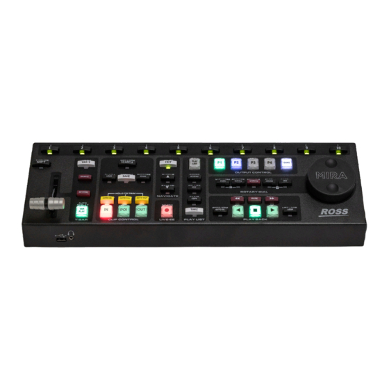
Replay Overview The Mira/Mira+ can operate as a replay server with the addition of the Mira Control Surface which allows quick interaction with the replay interface. Required Equipment To set up and operate your server you will need the following equipment: •... -
Page 90: Softkey Buttons And Shift
There is no power switch on the Control Surface. When you connect the Control Surface to the PoE Injector connected to the Control Surface port on the server the panel boots up. When the unit is up and running the softkey buttons along the top will illuminate, in order, from 1 to 10. -
Page 91: T-Bar Area
T-Bar Area • T-Bar – allows you to manually set the play speed of the clip playing out on the program channel transport. In default mode the range is from 0% play-speed at the bottom (towards you) and 100% play-speed at the top (away from you). -
Page 92: Navigate Area
• ERASE – press ERASE to erase the current clip. • RESTORE – press SHIFT > ERASE to undo the last erase. • GOTO IN – press GOTO IN to jump to the in-point of the clip. Tip: press GOTO IN during LIVE EE mode to mark a point of interest and rewind by the Auto-mark In-point offset •... -
Page 93: Play List Area
Play List Area • PLAY LIST — press PLAY LIST to put the selected playout channel in Play List mode. The button flashes in PL EDIT (Play List edit mode) and is solid PLAY LISTmode. Tip: In PL EDIT mode, press PLAY LIST to go to PLAY LIST mode and press the button again to jump to the first clip in the current Play List. -
Page 94: Rotary Dial Area
Rotary Dial Area • Rotary Dial – allows you to perform a variety of functions, depending on the selection to the left of the dial. By default, the rotary dial is used to jog through the video loaded in the channel transport. •... -
Page 95: Replay Window
• STEP – press SHIFT and STEP to reverse by a single field. • PAUSE – pause the playout of the current clip. • – press and hold to fast forward the clip, or press and release to jump a small interval. •... -
Page 96: Playout Channels
Playout Channels The playout channels are shown at the top of the window as the program outputs. The name that appears on each playout channel can be set from the user settings. You can select each playout channel using the P1, P2, P3, P4 buttons on the Control Surface, or the GANG button to select them all. -
Page 97: Modes Of Operation
The softkey labels are shown at the bottom of the window and correspond to the numbered buttons along the top of the Control Surface. To make a selection you can either click a softkey directly, or press the corresponding softkey button on the Control Surface. -
Page 98: Clip Play Mode
Clip Play Mode The Clip Play mode allows you to view any local clip on the server that is being played out one of the playout channels. These server clips can be played, added to a Play List, or saved and trimmed to Bank 0. Bank 0 is used to save server clips (Clip Library clips) so they can be trimmed and edited and made available in the replay modes. -
Page 99: Vue Mark Mode
Vue Mark Mode The Vue Mark mode allows you to view a list of marks made in the current replay event. Mark points show timecode, camera, and a name (if applied). Mira/Mira+ User Manual — Replay Overview • 99... -
Page 100: Replay Events
Replay Events A replay event puts the server into replay operation. The incoming video signals from the cameras are continuously being recorded for use in a replay. When an event you want to replay occurs, you can seek to the start of the action that you want to replay and play it out of one of the playout channels. - Page 101 10. In the Camera Name field, enter a name for each camera feed. 11. On the Camera Number list, select the number you want to assign to each camera feed. 12. Click Next. 13. You can apply preset names to replay clips from the Control Surface using the sofkeys. Set the names you would like to use as follows: a) In the Initial Name column, enter a prefix you want be able to apply to a clip name using the 8,9, or 10 sofkeys on the Control Surface.
-
Page 102: To Open A Replay Event On A Control Surface
14. Click Create Event. The replay event has been created in the Clip Library. 15. Click Start RECORDING. The replay event is now recording in the channel transport. 16. Click Finish. The recording channel shows it is recording the camera inputs. With the event created and recording, you can now open the event on the Control Surface to launch the replay operation interface. -
Page 103: To Open A Replay Event On Two Control Surfaces
To Open a Replay Event on Two Control Surfaces Open a replay event on two Control Surfaces to activate the replay interfaces. 1. In the Clip Library, right click on the replay event you want to open and click Open on Control Panel #2. 2. -
Page 104: Replay Operation
Replay Operation The replay operation uses a replay event that is opened on a Control Surface. The replay event requires channels on the server to be set to replay (ISO), and the Control Surface to be assigned to playout channels. A typical replay workflow involves importing clips you want use during the replay, capturing events, replaying them immediately or storing them for later, and export for archive or later use. -
Page 105: To Capture An Event For Live Replay
1. Press the PX button for the playout channel you want to send the live record video out of. Tip: You can press GANG to assign the Control Surface to all the playout channels (the borders around all the playout channels turn white). -
Page 106: Playback
2. Mark the clip when something interesting happens. You can either mark the point of interest (POI), end of the event (end-point), or start of the event (in-point). The remaining points are automatically marked according to the Auto- Mark In/Out point from the User Setup menu. •... -
Page 107: Clipping
2. Play the clip back at the desired speed. • Normal Speed — press to play the clip at normal speed. • T-Bar — move the T-bar to play the clip at a dynamic variable speed. The further you move the T-bar, the faster the clip plays. -
Page 108: To Name A Clip
5. Press LOAD to load the clip. The playout channel goes into CLIP PLAY mode and the in-point of the new clip is shown. The IN button lights red to indicate that you are looking at the in-point of the new clip. To Name a Clip Once a clip has been defined and saved you can name the cameras in the clip to organise them for future use. -
Page 109: To Trim A Clip
2. Use the keyboard to enter the number of the Bank (1-99) that you want to load the clip from in the ENTRY field and press SHIFT + LOAD. Note: Bank 0 is intended for Clip Library (server clips) that you want to make available for replay actions. 3. -
Page 110: Play List
Play List The Play List operation focusses on ordering and editing clips to be taken on-air in order and as a group, as a highlight reel for example. To Create a Play List Replay clips can be collected together into a Play List that can be taken on-air. 1. -
Page 111: To Edit A Play List
1. Press PLAY LIST > Edit Item Flags (10) > PLAY LIST Library (1). 2. Select the Play List that you want to name. 3. Use the keyboard to enter a new name in the ENTRY field. 4. Press NAME PLAY LIST (2). Tip: You can copy (COPY PL NAME (4)) and paste (PASTE PL NAME (5)) names from one Play List to another, or clear (CLEAR PL NAME (3)) the current name. -
Page 112: To Copy And Paste Play List Items
8. Set a different behaviour for the start (@START) of a clip if required. • Play — press @START (7) to toggle to PLAY in the Play List table. The clip plays out automatically when the playlist transitions to this clip in ON-AIR mode. This is the default setting. •... -
Page 113: To Air A Play List
1. Press PLAY LIST > SHIFT > AUDIO CONTROL (10). The playout channel goes into PL EDIT mode. 2. Press AUX AUDIO ENABLE (5) to toggle the feature on. 3. Press Mira Clip Library (3) and select the audio clip that you want to add to the Aux Audio list. 4. - Page 114 4. Select the Play List that you want to play and press PLAY LIST. The Play List is loaded and the playout channel is in PL EDIT mode. 5. Press PLAY LIST again. The playout channels are in PLAY LIST mode. In 2-channel playout you will notice that the first item in the Play List is cued in P1 and the second item in the list is cued in P2.
-
Page 115: Export/Melt
Export/Melt Content from a replay event can be saved and exported (melted) to a standard clip format that can be archived and played in normal server operation. Each Play List, or clip, included in the melt is exported to a separate media file. The replay event export/melt uses the same export method and destination folder as the export function of the server. -
Page 116: Mark
Mark You can quickly create a mark point of the active camera to mark an event that you can come back to later. Creating the mark point automatically creates a point of interest (POI), in-point, and out-point based on the Auto-Mark IN/OUT setting of the User Setup. - Page 117 5. Select a new point of interest as follows: a) Press GOTO POI. b) Use the rotary dial to select the new point of interest. c) Press POI. 6. Select a new out-point as follows: a) Press GOTO OUT. b) Use the rotary dial to select the new out-point. c) Press OUT.
-
Page 118: Export
Export You can export a clip from the Clip Library to a number of formats for use in an external device. Files are exported in the same video format that the server is operating in. Supported Media Files for Export Table 6: Supported HD Video Codecs File Type Codec... -
Page 119: To Select An Export Destination
To Select an Export Destination You can set up to nine export destinations, each with a different export format. Destination folders should only be located on network drives or high-speed USB drives (USB 2.0/3.0/3.1) mounted on the server. Important: Do not select an export destination on the system ( ) or media drive ( ) of the server. -
Page 120: To Export Media Files
12. Click Verify Export Destinations to verify that all destination can be found. A message is shown next to the button stating that all destination are valid, or that destinations are missing. The destinations that are missing are highlighted in yellow. 13. -
Page 121: Growing File Export
Growing File Export You can constantly export any channel that is being recorded, including one or more angles of a replay event, to an export location on network drives or network attached storage (NAS). The growing files can then be imported into a non- linear editor where is can be worked on in near real-time as the file continues to grow. - Page 122 2. Select Enable for the record channel that you want to set up the growing export for. Note: The options available depend on how the server is configured and whether the hardware channel has been set up for single- channel or multi-channel IOS operation. 3.
-
Page 123: Remote Control Support
Remote Control Support Use the information in this section to assist you in setting up an external device to control your server. Remote Communications (RS-422) Direct serial control of each channel transport on the server is available through the RJ45 ports on the breakout cable connected to the server. -
Page 124: To Configure A Room For The Odetics Protocol
5. In the Response Time area, select how quickly the server executes the Clip Play command after the Clip Load command. • Fast — executes the play command immediately after the load command. This is recommended when controlling the server from an external switcher. •... - Page 125 2. Click the RS422 tab. 3. Click Room X Configuration and select the room you want to configure. Later you will assign this room to a channel. 4. In the RS422 Protocol area, select Odetics. 5. In the Response Time area, select how quickly the server executes the Clip Play command after the Clip Load command.
-
Page 126: To Configure A Room For The Vdcp Protocol
8. In the Odetics Protocol Configuration area at the bottom of the window, select specific configurations for the protocol you are using. • Select Disable field timecode reporting to force the server to report timecode only once every video frame. If this option is not selected, the server reports timecode every field. -
Page 127: To Configure A Room For The Amp Protocol
6. In the Response Time area, select how quickly the server executes the Clip Play command after the Clip Load command. • Fast — executes the play command immediately after the load command. This is recommended when controlling the server from an external switcher. •... - Page 128 2. Click the RS422 tab. 3. Click Room X Configuration and select the room you want to configure. Later you will assign this room to a channel. 4. In the RS422 Protocol area, select AMP. 5. In the Response Time area, select how quickly the server executes the Clip Play command after the Clip Load command.
-
Page 129: Dashboard
The DashBoard control system allows remote access to multiple pieces of Ross Video equipment, including openGear ® cards, Carbonite production switchers, Ross video servers, and Ross cameras. Download and install the latest version of DashBoard from www.rossvideo.com/support/software-downloads/. Review the documentation that comes with DashBoard for information on installing and launching DashBoard. -
Page 130: Maintenance
Maintenance Refer to the following information for performing maintenance on your server, muting an alarm, restoring factory defaults, or upgrading the software. Media Drives The server uses a RAID array of media drives to store all media content. Disk Space The amount of free disk space that is available for clips is shown at the top of the Mira Explorer window. -
Page 131: Troubleshooting
Troubleshooting Refer to the applicable section below for information on troubleshooting the operation or setup of your server. Mira Explorer Problems • Transport control buttons (Play, Stop, etc.) are grayed out. • If a replay mode is active, only those channel transports that are not used for the replay will be available. •... - Page 132 • If the power supply checks okay, check the LEDs on the SSD drive on the front of the server. These LEDs should be BLUE or PURPLE. If any of the LEDs are RED there may be a failed SSD drive. Contact Ross ®...
-
Page 133: Specifications
Specifications Resources, video specifications, power rating, and port pinouts. The information is this section is subject to change without notice. Resources The number of resources specific to your server depends on the model. Resource 4-Ch 8-Ch 12-Ch Video Inputs Video Outputs AES Audio Inputs AES Audio Outputs Analog Audio Outputs... -
Page 134: Ports
Ports Serial (RS422) Port The female DB9 serial connectors on the RS422 Control Breakout Cable support the RS-422 transmission standard. Signal Ground Rx-Ground Tx-Ground LTC Port Signal Ground LTC- LTC+ AES Audio Port There are two AES audio ports on the back of the server providing 8-track AES inputs and outputs. Each AES input and output can be assigned to an available video channel using the Audio Router (refer to Audio Router Setup on page 18). - Page 135 Mira/Mira+ User Manual — Ports • 135...
-
Page 136: Index
Index Numerics Cue Points 2-Replay Channel Transition, User Setup 2X VK 3-Point Loop 69, Delete Clip 3D ISO2 Dim for Lists, User Setup 3D ISO3 Disk Space 3G Formats Duplicate Segment, Export 3X VK + 2V 3X VK + VK 4X VK Edit Replay Event Template Eject Clip... - Page 137 Import, Multi-Screen Mira Config Import, Watch Mira Explorer Initial Names, User Setup Mira Import ISO Channel Modes Mix Transition Duration, User Setup ISO10 Modes ISO11 Modify Replay Event ISO12 Multi-Screen Import ISO2 ISO3 ISO4 ISO5 Names, User Setup ISO6 ISO7 ISO8 ISO9 Obey Clip Out-point, User Setup...
- Page 138 Record 68, UnLoad Clip Remote Control 123, Use 2 Channels for PL mode, User Setup Remove Watch Folder User Setup Repeat Modes User Setup File, Load Replay Event, Melt 115, User Setup File, Save Replay Panel, connecting User Setup Files Replay Setup 28, Replay Window Replay, Two Users...
Need help?
Do you have a question about the Abekas Mira and is the answer not in the manual?
Questions and answers