Table of Contents
Advertisement
Quick Links
Advertisement
Table of Contents

Related Manuals for ROOTS MACRO M60


Summary of Contents for ROOTS MACRO M60
-
Page 2: Table Of Contents
P/N: 571001082-00, Rev-A, 07/2017 Sommario Sommario ............................2 Chapter 1 Preamble ........................... 2 1.1 IDENTIFICATION OF THE MACHINE 1.2 DECLARATION OF CONFORMITY 1.3 IDENTIFICATION OF MANUFACTURER 1.4 OTHER MANUALS OF REFERENCE 1.5 GENERAL WARNINGS 1.6 USE AND MAINTENANCE MANUAL 1.6.1 PURPOSE ..............................4 1.6.2 PRESERVATION ............................ - Page 3 3.4 DESCRIPTION OF THE MACHINE 3.4.1 Chassis ............................15 3.4.2 Endothermic Engine ........................16 3.4.3 Cabin ............................. 19 3.4.4 Waste hopper ..........................20 3.5 OPERATION OF THE MACHINE 3.5.1 Hydrostatic traction ........................21 3.5.2 Traction axle ..........................22 3.5.3 Steering ............................22 3.5.4 Brakes ............................
- Page 4 4.5 BRAKING SYSTEM PRESSURE GAUGES 4.6 SWEEPER COMMANDS 4.6.1 Hydraulic commands control panel ..................... 48 4.6.2 SWEEPER CONTROL PANEL ........................49 4.6.3 SWEEPER INDICATOR LIGHTS ....................... 50 4.6.4 3RD BRUSH CONTROL PUSH-BUTTON PANEL (OPTION) ..............51 4.7 AIR CLIMATE SYSTEM CONTROL PANEL 4.8 INSTRUCTION FOR USE 4.8.1 STARTING THE ENGINE .........................
- Page 5 5.3.10 CHECK THE CLEANLINESS OF THE ENGINE RADIATOR FINS ............15 5.3.11 CHECK THE CLEANLINESS OF THE AIR CLIMATE RADIATOR ............16 5.3.12 WASH THE VERTICAL LOADER MECHANISM ................17 5.3.13 WASH THE WASTE CONTAINER ....................17 5.3.14 GREASING OPERATIONS ......................19 5.3.15 CHECK ENGINE COOLANT LEVEL ....................
- Page 7 "OPERATOR" means the person responsible for the installation, the operation, the adjustment, the maintenance, the cleaning, the repair and the transport of the machine. The company Roots Multiclean Ltd. will not consider itself as responsible for troubles, accidents, etc. due to the bad knowledge of the procedures contained in this Manual.
-
Page 8: Sommario
Preamble Chapter 1 1.1 IDENTIFICATION OF THE MACHINE The machine is identified by the CE Marking prepared according to the specifications of Machinery Directive 2006/42/EC and subsequent amendments. The following figure shows an example of an ID plate for the machine, which is riveted on the right side of the inner bonnet, in front of the driver's seat. Pict. -
Page 9: Declaration Of Conformity
1.2 DECLARATION OF CONFORMITY Each machine is provided with the Declaration of Conformity. Roots Multiclean Ltd..guarantees compliance of its machine with the directives mentioned and affixes the marking on the machine itself. Below is an example of a Declaration of Conformity for the M60 type operating machine Certifichiamo la conformità... -
Page 10: Identification Of Manufacturer
1.4 OTHER MANUALS OF REFERENCE • Operating Instructions Manual for Diesel Engine OM 904 LA. INFORMATION Roots Multiclean Ltd. being committed to continuous product and quality development, reserves the right to modify the data contained in this publication at any time. 1.5 GENERAL WARNINGS This chapter contains some warnings that allow you to properly use the machine without danger for the Operators and property. -
Page 11: Preservation
– not remove, add, modify or rewrite any part of the Manual; any changes to it shall only be made by Roots Multiclean Ltd., – keep the manual in areas protected from moisture, so as not to jeopardize its durability;... -
Page 12: Duties Of The Employer
The employer is responsible for disclosing this document to all personnel that will interact with the machine. The employer also commits to update the manual with the parts that Roots Multiclean Ltd.. will send in the case of changes to the machine. In the case of loss or destruction of the manual, the employer commits to request the missing parts or the full manual to Roots Multiclean Ltd. -
Page 13: Precautions To Be Observed With Engine Running
– Engine maintenance must be carried out with the engine cold. – Do not smoke while pouring fuel. – Keep flames and sparks away from the machine. For the machine: – For the machine to travel on public roads, it must have vehicle registration documentation and a number plate for operating machine. -
Page 14: Caution Signs
1.12 CAUTION SIGNS There are CAUTION stickers affixed on the machine. It is compulsory to acknowledge them before any use. In the event of non-indelible stickers, remember to replace them when reading becomes difficult. 1 - 8... -
Page 15: Chapter 2 Transport, Handling, Installation
Chapter 2 Transport, Handling, Installation DANGER Disclose the Instructions in this chapter to all personnel involved in the transportation and handling of the machine. INFORMATION It is essential, for this purpose, to print this chapter in single volume to make it accessible to Operators. - Page 16 For proper unloading and handling, we recommend the presence of two Operators equipped with Safety Helmet, Gloves and Safety shoes. These Operators must pay the utmost attention during all transport stages and stay a safe distance from the machine when close proximity is not strictly necessary. DANGER Prohibit any person from standing close in order to avoid contact with any projected parts and objects in case of an accidental fall.
- Page 17 Pict. 2-3 Control Panel – Ensure the central brush is lifted. – Ensure the side brushes are lifted and blocked (par. 3.10.1). – Select the driving direction using the lever right of the steering wheel (DEV2). 1 - 11...
- Page 18 Pict. 2-4 Controls/Indicators on dashboard – Press the accelerator to move, climbing onto the vehicle transporter. Pict. 2-5 Move the Machine onto the vehicle transporter – Once having reached the correct position, stop the machine and engage the parking brake. DANGER Make sure the machine is properly secured to the trailer by means of suitable ropes, using the appropriate connections on the reaction rod supports of the frame.
-
Page 19: Packaging
Pict. 2-6 Hooking points for the safety ropes (1 of 4) Unloading must be carried out by following the operations in reverse order. 2.2 PACKAGING Any packaging must be disposed of by the user according to the standards in force in his/her country. 2.3 INSTALLATION The machine is delivered fully assembled and perfectly operational, so it is not necessary for the customer to perform installation operations. -
Page 20: Chapter 3 Description Of The Machine And Technical Features
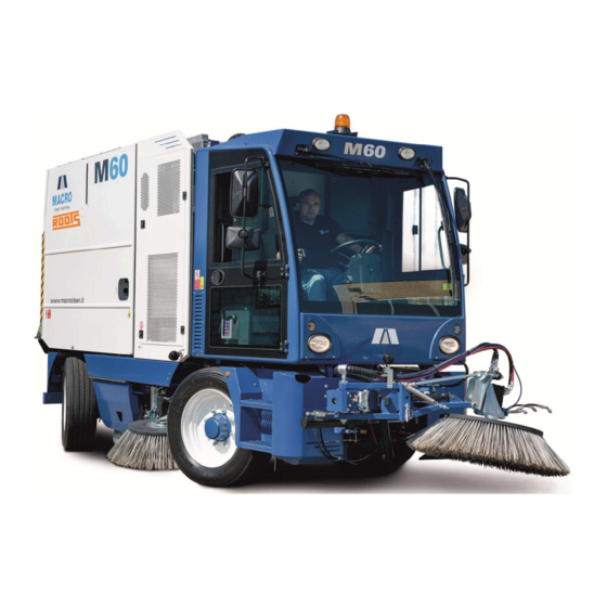
Description of the Machine and Technical Features Chapter 3 3.1 NAME OF THE MACHINE The machine is called: M60 Mechanical - Suction Street Sweeper. 3.2 FORESEEN USE The M60 Mechanical - Suction Street Sweeper has been designed to perform a complete cleaning cycle of urban areas: sweeping, collection and discharge of material collected. - Page 21 Pict. 3-1 M60 Machine 3.4 DESCRIPTION OF THE MACHINE 3.4.1 Chassis a) Structure The structure has been designed to have a flexible torsion resistance appropriate for loading and unloading at a height. The chassis in high resistance steel is open at the side, with a central ring formed by closed profiles.
-
Page 22: Endothermic Engine
Pict. 3-2 Tyres c) Rear under ride protection bar The rear under ride protection bar is formed by two components: a metal bumper, that is also used as a light holder and licence plate holder, and an internal structural reinforcement. Pict. - Page 23 Pict. 3-4 Engine plate (Power 110 kW) a) Lay-out The engine is behind the cabin with the flywheel facing the left side of the machine; it is fixed with elastic supports to a metal structure that also supports the radiator and hydraulic oil tank. Pict.
- Page 24 Pict. 3-6 Fuel tank cap (RH side) Fuel pre-filter with heater for very low temperatures and manual pump power. Fuel cartridge filter including fittings with check valves to facilitate filter changing. d) Cooling circuit Closed circuit with expansion tank in steel placed over the radiator. The honeycomb aluminum radiator is positioned in line with the engine on the right side of the machine.
-
Page 25: Cabin
3.4.3 Cabin The cabin has the distinction of having the driver's seat in a central position and two additional seats next to the driver. The cabin is connected to the chassis with specific vibration dampers, and has a closed profile metallic structure with metal buffer sheets of suitable thickness. It is painted with a preventive catachresis treatment. -
Page 26: Waste Hopper
3.4.4 Waste hopper The hopper is shaped to convey the litter to the centre during tipping. Inside it has, in separate compartments, the water tank and the bag filter. Tipping is via a telescopic hydraulic cylinder. The closing hatch is also hydraulically commanded. Pict. -
Page 27: Operation Of The Machine
Pict. 3-12 Safety stop not inserted Safety stop inserted 3.5 OPERATION OF THE MACHINE 3.5.1 Hydrostatic traction a) General description Traction takes place on the front axle and is obtained through an automotive type hydrostatic system, i.e. a self-adaptive system that simulates operation of a mechanical automatic transmission in a context that is however fully hydraulic. -
Page 28: Traction Axle
converts it into mechanical energy, although using only hydraulic drives. • Control unit Parameter management is done through customizable mappings in which all the input data are processed according to the response required. The electronic part is complete with different pressure and rev sensors. -
Page 29: Cleaning System
3.6 CLEANING SYSTEM 3.6.1 General information M60 is designed for cleaning large hard surfaces (roads and other), but with special regards for tight spaces. In fact, its size (especially the pitch) outlines its vocation for awkward spaces such as city centres, although it appears to be a complete machine and very spacious. -
Page 30: Main Components Of The Cleaning System
3.6.4 Main components of the cleaning system Pict. 3-13 Cleaning system a) Central brush Cylindrical in shape, the symmetrical roller has a track width of 1300 mm and a diameter of 500 mm; it can be provided with mixed or only PPL bristles that are cusp-shaped or full. Moved via a hydraulic engine, it is supported by a pneumatic system that optimizes the pressure on the ground. -
Page 31: Information On The Brushes
system. It is formed by a canvas in PE that forms the bags with the hydraulically commanded shaker system fixed to the ends. f) Fan-vacuum The fan located in the rear upper part of the waste hopper is moved by a hydraulic engine adapted to the specific requirement. - Page 32 Pict. 3-15 Dust-proof device The water is stowed in a tank in AISI 304 steel placed at the upper end of the waste hopper. It has a capacity of about 620 l and is rechargeable via a convenient hose. By using horizontal tanks the capacity reaches 1220 litres.
-
Page 33: Hydraulic System
The water level can be visually controlled via a level on the right side of the machine. Pict. 3-17 Water level The pressure for spraying is supplied by a medium pressure pump. Management of the water flow is commanded by some buttons on the control panel on the armrests. The machine can be equipped (optional) with a high pressure washing lance with 10 metres of hose, mounted on a spring winder. -
Page 34: Electric System
Pict. 3-18 Oil level 3.9 ELECTRIC SYSTEM 3.9.1 General description The system is made according to the most modern methods in use in the automotive sector. It uses a series of control units with 32 bit processor with analogue and digital output, and also in CAN. They are certified in compliance with IEC 61508 and with IP69 degree of protection EN60529. -
Page 35: Lights
Pict. 3-19 Batteries Pict. 3-20 Battery release 3.9.3 Lights On the M60 machine 4 headlights are mounted: 2 road lights with H4 halogen bulbs and 2 work lights with H3 halogen lamps. Another 2 led work lights are mounted on the side brushes. There is also a led work light on the third brush, if present. - Page 36 DANGER Do not adjust the steering column whilst driving. Driving with the steering column unlocked can result in loss of control of the vehicle by the driver. Ensure that the steering column is locked before driving the vehicle. Pict. 3-21 Steering column 1 - 30...
- Page 37 Pict. 3-22 Command switches and instrument panel Pict. 3-23 Display instrument change push-button 1 - 31...
-
Page 38: Sweeping Controls And Command
3.9.5 SWEEPING CONTROLS AND COMMAND Pict. 3-24 Control Panel All the sweeping functions can be operated from panels distributed around the driver . • Control Panel, located above the driver seat and including 6 manual commands for the control of the machine working functions and a Signal Panel. -
Page 39: Safety Systems
Pict. 3-26 Sweeping hydraulic control panel 3.10 SAFETY SYSTEMS The devices used to ensure complete safety are as follows: – For the travel phase, all sweeping and suction elements are equipped with locking devices that keep them in a raised position even during the absence of control energy; –... - Page 40 ATTENTION The following operations must be performed with the machine at a standstill. Command lifting of the brushes, taking them to the position illustrated in Pict. 3-27, – insert the pin – lock the pin in the rear part with the safety plug. In the Work phase, the Operator must: –...
-
Page 41: Safety Devices For 3Rd Brush (If Present)
Pict. 3-28 Safety pin position with brushes in Work Pict. 3-29 Plug non inserted Plug inserted 3.10.2 SAFETY DEVICES FOR 3RD BRUSH (if present) a) Safety against accidental lowering of brush The machine is equipped with a safety stop, on the arm of the 3rd brush, that prevents involuntary lowering of the brush during the Travel phase. - Page 42 – insert the pin in the position indicated in Pict. 3-35, thereby freeing the brush arm, – reposition the pin's safety plug. Pict. 3-30 Safety pin position with the 3rd brush in Travel Pict. 3-31 Position the safety pin with the 3rd brush in Travel: pin inserted 1 - 36...
- Page 43 Pict. 3-32 Safety pin position with 3rd brush in Work b) Safety for 3rd brush arm rotation The machine is equipped with a safety stop, on the arm of the 1st arm of the 3rd brush, that: – forms the arm anti-rotation lock during driving on the road –...
-
Page 44: M60" Main Technical Data
Pict. 3-34 Safety stop inserted 3.11 "M60" MAIN TECHNICAL DATA Technical data Basic machine length 5240 Front overhang 1300 Rear overhang 1040 Pitch (distance between the 1st and 2nd axle) 2900 Width 1870 Maximum height of load to the rotating light 2910 Maximum height of load to the structure 2830... - Page 45 Variations in the dimensions with third brush and rear vacuum tube Total length 6120 Front overhang 2030 Rear overhang 1210 Overall dimension radius to the right 5540 Overall dimension radius to the left 5140 Weight Total weight of basic machine, empty, with full fuel tank and operator on board 7400 Total weight at full load...
- Page 46 Stroke Capacity 4.25 litres Engine Effective maximum power 110 kW @2200 rpm Maximum speed 2600 Maximum torque 580 Nm from 1200 to from 1200 to 1600 rpm Cooling liquid Hourly consumption gr/kWh Fuel (**) Diesel in accordance with DIN Fuel tank Capacity litres AdBlue tank Capacity n.a.
-
Page 47: Dimensions
With RH, LH and central brushes 2700 With third brush Ø 1000 3600 With third brush Ø1200 (and speciale adjustment kit) 3700 With central brush only 1300 (**) The OM904 engine can operate with Biodiesel or FAME fuel that complies with Standards DIN E 51606 or EN 14214. -
Page 48: Environmental Values
Pict. 3-36 Overall dimensions of machine complete with accessories 3.13 ENVIRONMENTAL VALUES 3.13.1 MANUFA CTURING The environment must be well-lit and there must be no danger of explosion of any kind. DANGER To avoid the risk of hazardous inhalation caused by exhaust gases, the machines must only be used in environments with adequate ventilation. -
Page 49: Chapter 4 Use
emptied. Chapter 4 DANGER The machine must be used ONLY by personnel who are familiar with the operation of all its controls. INFORMATION Before starting the machine, check that the battery charging, engine oil pressure and parking brake warning lights are lit. 4.1 TRAVEL CONTROLS The controls used for the road travel function of the M60 machine are mainly on the steering column. -
Page 50: Commands On Steering Column
4.2 COMMANDS ON STEERING COLUMN FORWARD DEV1 DEV2 REVERSE Pict. 4-2 Commands on steering column General command to turn on the parking lights and the low lights Working lights command / lamp Parking brake command / lamp Screenwiper command Rear fog lamp command ECOPOWER control button with safety lock (optional) Emergency lights switch Engine start/stop command (with key) -
Page 51: Parking Brake
4.3 PARKING BRAKE The parking brake command is on the dashboard of the steering column (Pict. 4-3) It is a switch with safety lock to prevent undesired entry while driving the machine. Pict. 4-3 Parking brake switch While driving on-road, with the brake off, the switch is turned towards the right. To insert release the safety lock and push the switch to the left, insertion is indicated by the red indicator light. -
Page 52: Dashboard Warning Lights And Gauges
4.4 DASHBOARD WARNING LIGHTS AND GAUGES Pict. 4-4 Signal panel on dashboard Direction indicator lamp (green) Working lights lamp Parking lights lamp (green) Not used Not used Gear engaged lamp Fuel level lamp (reserve) Lamp "Check Engine" Lamp STOP 10 Air filter clogging lamp 11 Water temperature lamp 12 Engine oil pressure lamp 13 Generator lamp... -
Page 53: Braking System Pressure Gauges
4.5 BRAKING SYSTEM PRESSURE GAUGES Pict. 4-5 Brakes pressure gauges Front braking system pressure gauge Front braking system insufficient pressure warning light Rear braking system pressure gauge Rear braking system insufficient pressure warning light Parking brake pressure gauge Parking brake insufficient pressure warning light Central broom pressure gauge Vertical loader pressure gauge DANGER... -
Page 54: Sweeper Commands
4.6 SWEEPER COMMANDS 4.6.1 Hydraulic commands control panel Pict. 4-6 Sweeping control block 3 position lever selector: - Lh: Command to raise and stop the central brush and the vertical loader - 0: Neutral - Rh: Command to lower and rotate the central brush and the vertical loader 3 position lever selector: - High: Command to lower and rotate the left lateral brush... -
Page 55: Sweeper Control Panel
- Low: Command to open the deposits door Command for left lateral brush anti-dust nozzles water (subjected to activation of water pump on Sweeping Command Panel) Pict. 4-7 pos. 5 and increases, if rotated in clockwise direction, the water quantity. Command for third brush anti-dust nozzles water (if present) (subjected to activation of water pump on Sweeping Command Panel) Pict. -
Page 56: Sweeper Indicator Lights
7. Sweeping functions indicators 4.6.3 SWEEPER INDICATOR LIGHTS Working mode trip hour-counter Pict. 4-8 Sweeping function signals 1. Red light - Back hatch open 2. Red light - Container up 3. Red light - Hydraulic oil lever 4. Red light - Transport locked 5. -
Page 57: 3Rd Brush Control Push-Button Panel (Option)
4.6.4 3RD BRUSH CONTROL PUSH-BUTTON PANEL (OPTION) Pict. 4-9 Third brush control push-button panel 1. Slope command switch – Slope orientation to left – Sloper orientation to right 2. First arm shifting – Movement of 1st arm to left – Movement of 1st arm to right 3. -
Page 58: Air Climate System Control Panel
4.7 AIR CLIMATE SYSTEM CONTROL PANEL Pict. 4-11 Air climate control unit 1. Ambient temperature setting. – Arrow Up: increases the temperature. – Arrow Down: decreases the temperature. 2. Set/external temperature display. 3. Air fan speed display LED (LO, MED, HI). 4. -
Page 59: Instruction For Use
4.8 INSTRUCTION FOR USE 4.8.1 STARTING THE ENGINE – Sit on the driver's seat. – Adjust the position of the steering column to adapt it to the driver. Use the lock/unlock handle on the steering column (Pict. 4-12 pos. 1). DANGER Do not adjust the steering column whilst driving. - Page 60 Pict. 4-14 Parking brake – Make sure the lever for selection of the driving direction is in the central position (Pict. 4-15 pos. INFORMATION If the parking brake is not activated and the lever for selection of the driving direction is not in the central position, the engine will not start.
-
Page 61: Travel Mode
On the signal panel the battery charging (neutral) and parking brake warning lights must be lit. The Check Engine warning light remains on for a few seconds. – Turn the key clockwise to "Engine Ignition" until the engine is started; INFORMATION At engine start, check that the battery charging, check engine and oil pressure warning lights are off. -
Page 62: Operation Mode For Side And Central Brushes
4.8.2 Travel mode With engine started, perform the following operations: INFORMATION If the selection lever of the driving direction is not in the central position, the travel position will not be activated. – Check that the safety devices for the side brushes and the 3rd brush, if present are inserted (see 3.10.1 and 3.10.2) –... - Page 63 which controls: – the lowering and the rotation of the central brush; – the engage of the vertical loader movement; • Do the regulation of central broom pressure to the ground using the light blue knob (Pict. 4-18 pos.8) : rotate counterclockwise if you want to increase pressure otherwise rotate clockwise if you want to decrease the pressure to the ground of the bristles.
- Page 64 clockwise direction increases the speed while, acting in counterclockwise direction, decreases the brush rotation speed. engage engage right left Speed Pict. 4-19 Side brush commands 3. Activation of the water nozzles Pressing the switch (Pict. 4-17 pos. 5) of the Command Panel, the water pump activates. The control of the water delivery, through the nozzles located over the brushes, is controlled by the sweeping control block by means of knobs 8 (for left side brush), 9...
-
Page 65: Suspension Of Activity
operation can be executed only with engine off. 4.8.4 SUSPENSION of ACTIVITY In Operation mode, when reverse is inserted: • the rear camera with view of the pictures on the display video is automatically activated. • Please raise the central and the side brushes if you need to stay in reverse for a long time to save bushes from damages. -
Page 66: Clean Pollution Filter Before Discharge Debris
If the hopper hatch is not closed correctly, the danger sign is lit on the Control Panel (Pict. 4-8 pos. 1). – Once the hopper has been emptied, lower it with the following operations: • Lower the hopper • Recall the hopper •... -
Page 67: Safety Devices
– engage the parking brake (see par. 4.3) – switch off and remove and the ignition key – At the end of the work clean carefully the sweeper (see Chapter 5) 4.9 SAFETY DEVICES There are some safety devices on the tipper's various utilities, and more precisely: –... - Page 68 Pict. 4-21 Camera Pict. 4-22 Monitor 1 - 62...
-
Page 69: Use Of 7" Wide Tft Lcd Monitor
4.11 USE OF 7” WIDE TFT LCD MONITOR Pict. 4-23 Camera monitor commands 1. Power supply switch 2. Menu command key 3. Enter key 4. Channel up key 5. Channel down key 6. Volume down key 7. Volume up key 8. -
Page 70: Details Of The Functions Menu
On the NV channel the sequence is the same as the one below without the OSD menu CAMERA FUNCTION PICTURE * Clear up OSD. 3. Enter Key • After having positioned the cursor of the FUNCTION & CAMERA OSD Screen of the set- up menu, use CHANNEL UP/DOWN keys to select the desired mode to be activated with the ENTER key •... - Page 71 OFF: Disable the AUTO DIMMER function. • LANGUAGE : 5 Languages available ENGLISH, GERMAN, FRENCH, ITALIAN, SPANISH – Position the cursor on LANGUAGE with the CHANNEL Up/Down keys – Select the desired language with the ENTER ENGLISH key : Factory default •...
-
Page 72: Cabin Handling Mechanism
0-100 / 50: Factory default • TONE – After having positioned the cursor on TONE, use the Volume Up/Down keys to adjust the tone 0-100 / 50: Factory default 3. Camera • Distance Marker in rear view – Display the CAMERA menu by pressing 3 times the MENU key and positioning the cursor on CAM DIST with the Volume Up/Down keys. -
Page 73: Towing The Vehicle In An Emergency
Pict. 4-24 Cabina handling – Insert the lever (a) in the jack (b) – Rotate the slider clockwise (position c) and use the lever (a) to lift the cabin. – Rotate the slider anticlockwise (position d) and use the lever (a) to lower the cabin. 4.13 TOWING THE VEHICLE IN AN EMERGENCY If it is impossible to use the engine, for failure or other specific condition, the machine can be towed only by performing a by-pass operation of the engine/pump unit. - Page 74 ATTENTION Move the machine at a maximum speed of 5 km/h Pict. 4-25 Traction Pump For towing the machine, use of a vehicle of sufficient performance able to tow it (lorry) using a rigid bar hooked into the appropriate connection is required (Pict. 4-26 pos. c). Pict.
- Page 75 1 - 69...
-
Page 77: Chapter 5 Cleaning And Maintenance
Cleaning and Maintenance Chapter 5 5.1 Genera l Information INFORMATION Before starting the machine, on the dashboard signal panel, check that the battery charging, oil pressure and parking brake light indicators are lit. Cleaning the machine can be carried out by personnel without specific technical skills but they should be properly trained on the main cutoff commands of power sources and be familiar with the main features of the machine in order to avoid any hazardous situations. - Page 78 key removed).Wait for all mechanisms to stop and to cool down. Carefully read all the instructions in par. 1.10, before carrying out maintenance. The service life of the machine and maximum operating safety are ensured by a careful and regular maintenance.
- Page 79 Front traction axle: 9 [lt] 1.5 [lt] every wheel [AGIP Rotra MP/S 85W-90] unit 6 [lt] differential Hydraulic circuit Hydraulic oil: 200 [lt] Full load: 230 [lt] [AGIP ARNICA 46] Greasing circuit Lithium-based grease (Pb free) loading cont. 5 [kg] [AGIP Grease MU EP] Tab.
- Page 80 Pict. 5-1 Engine oil level 5. Take out the dipstick and check that the level is between the MIN and MAX level (Pict. 5-2); 6. If required, top up the level by means of the cap located on the upper part of the engine until the MAX level is reached.
-
Page 81: Checking The Battery Fluid Level
Pict. 5-2 Level reference 5.3.2 CHECKING THE BATTERY FLUID LEVEL ATTENTION Adequately protect body parts (eyes, hair, hands, etc..) when carrying out checks or cleaning the battery. 1. Operate the parking brake (see par. 4.3). 2. Turn off the engine by turning the ignition key anticlockwise to the stop position, then remove it. 3. -
Page 82: Check The Tire Pressure
Pict. 5-4 Batteries 5. Remove the protective cover and check that the connections of the battery terminals are not oxidized (Pict. 5-5). 6. If necessary, clean the contacts with the special wire brush. 7. Reposition the cab following the procedure described in 4.12. Pict. -
Page 83: Check The Oil Level In The Hydraulic System
Pict. 5-6 Tyre inflating valve 4. Using a pressure gauge (Pict. 5-7) measure the tyre pressure 5. The tyre pressure should be as follows: • front tyres: 8.50 Bar (123 psi) • rear tyres: 8.50 Bar (123 psi) Pict. 5-7 5.3.4 CHECK THE OIL LEVEL IN THE HYDRAULIC SYSTEM DANGER Check to be carried out with waste container completely lowered. -
Page 84: Clean The Water Filter In The Dust Suppression System
Pict. 5-8 Oil level check 4. If necessary unscrew the cap (Pict. 5-9 pos. a) and top up. To access the oil filler cap of the hydraulic system you must first obtain a suitable ladder. For the types of oils that can be used, see Chapter 3. -
Page 85: Cleaning Of The Nozzles Of The Dust Damp System
INFORMATION When the filter is removed, the water contained in the tanks comes out, so it is advisable to carry out this maintenance procedure when the water tanks are empty. 1. Operate the parking brake (see par. 4.3). 2. Turn off the engine by turning the ignition key anticlockwise to the stop position, then remove it. 3. - Page 86 Pict. 5-11 Pict. 5-12 4. Recover and using a jet of compressed air clean the nozzles (Pict. 5-13) of any impurities. Remove any limescale deposits. 5. Fit the nozzles and secure them with the lock nuts. 2 - 10...
-
Page 87: Check The Slides
Pict. 5-13 5.3.7 CHECK THE SLIDES 1. Operate the parking brake (see par. 4.3). 2. Lift the suction inlet (Pict. 5-14), operating as provided for in the relevant section. 3. Turn off the engine by turning the ignition key anticlockwise to the stop position, then remove it. 4. - Page 88 4. Unhook the 4 clips securing the cover (Pict. 5-16 pos. a). 5. Remove the cover Pict. 5-16) Pict. 5-16 Pict. 5-15 Pict. 5-17 6. Remove the filter (Pict. 5-18 and Pict. 5-20). 7. With a jet of compressed air (maximum 6 bar), clean the filter thoroughly by blowing from the inside out (in the opposite direction to the flow of the intake air).
- Page 89 Pict. 5-19 Pict. 5-18 Pict. 5-20 10. Assemble the prefilter (Pict. 5-21) being careful to insert the tab (Pict. 5-21 pos. a) in the notch present in the container (Pict. 5-22 pos. a). 11. Insert the filter 12. Install the cover and hook it by means of the fixing clips. ATTENTION Ensure the cover is fixed correctly! 2 - 13...
-
Page 90: Check The Cleanliness Of The Hydraulic Oil Radiator Fins
Pict. 5-21 Pict. 5-22 5.3.9 CHECK THE CLEANLINESS OF THE HYDRAULIC OIL RADIATOR FINS DANGER Appropriately protect body parts (eyes, hair, hands, etc..) when cleaning using compressed air or water guns. 1. Operate the parking brake (see par. 4.3). 2. Turn off the engine by turning the ignition key anticlockwise to the stop position, then remove it. 3. -
Page 91: Check The Cleanliness Of The Engine Radiator Fins
Pict. 5-23 Hydraulic oil radiator ATTENTION When washing with high pressure spray gun do not get too close in order. to prevent damage to components and radiator fins. 5.3.10 CHECK THE CLEANLINESS OF THE ENGINE RADIATOR FINS DANGER Appropriately protect body parts (eyes, hair, hands, etc..) when cleaning using compressed air or water guns. -
Page 92: Check The Cleanliness Of The Air Climate Radiator
Pict. 5-24 Engine radiator assembly Pict. 5-25 Engine cooling fan ATTENTION When washing with high pressure spray gun do not get too close in order. to prevent damage to components and radiator fins. 5.3.11 CHECK THE CLEANLINESS OF THE AIR CLIMATE RADIATOR DANGER Appropriately protect body parts (eyes, hair, hands, etc..) when cleaning using compressed air or water guns. -
Page 93: Wash The Vertical Loader Mechanism
Pict. 5-26 Air climate radiator ATTENTION When washing with high pressure spray gun do not get too close in order. to prevent damage to components and radiator fins. 5.3.12 WASH THE VERTICAL LOADER MECHANISM DANGER Appropriately protect body parts (eyes, hair, hands, etc..) when cleaning using compressed air or water guns. - Page 94 2. Fully tip the waste container and unlock the door. 3. Turn off the engine by turning the ignition key anticlockwise to the stop position, then remove it. 4. Wash the hopper using high pressure gun ATTENTION When washing with high pressure spray gun do not get too close to dust suppression filter in order.
-
Page 95: Greasing Operations
5.3.14 GREASING OPERATIONS Please carry out every 15 hours worked Pict. 5-29 REAR LEFT FRAME LUBRICATION POINT Pict. 5-30 REAR RIGHT FRAME LUBRICATION POINT Pict. 5-32 3 BRUSH LUBRICATION POINT Pict. 5-31 FRONT FRAME LUBRICATION POINT 5.3.15 CHECK ENGINE COOLANT LEVEL 1. -
Page 96: Replacement Of The Cab Air Filter
Pict. 5-33 Engine coolant level sensor If necessary refill coolant 5. Slowly open the cap of the engine cooling system and release the excess pressure. The correct proportion of anti-corrosion liquid and anti-freeze in the coolant, equal to 50%, occurs in the presence of an anti-freeze protection up to -37°C. -
Page 97: Replacement Of Fuses
Pict. 5-35 Pict. 5-34 Pict. 5-36 Pict. 5-37 5.3.17 REPLACEMENT OF FUSES The fuses protect the electrical system by intervening in the event of failure or improper action on the system. When a device does not work, you need to check the efficiency of its protection fuse: the conducting element of the fuse must not be interrupted. - Page 98 DANGER Never replace a blown fuse with metal wires or other recovery material. FIRE HAZARD. Never replace a fuse with another with a higher amperage. FIRE HAZARD. Before replacing a fuse, be sure to remove the key from the ignition and turn off/disable all users.
- Page 99 Pict. 5-40 Electrical system lay-out Pict. 5-41 Electronic units and communication ports 2 - 23...
- Page 100 Name Function Name Function R1.1= Air conditioning relay FUS1= TTC200 supply protection fuse(+30) R1.2= Fans air conditioning relay FUS.GEN.= Main Power supply fuse Tab. 5-5 Main fuse R1.3= Hidraulic oil electricfan relay R1.4= Oil heater relay R2.1= H2o pump relay R2.2= Start relay R2.3=...
-
Page 101: Brush Pressure Adjustment
F3.5= 3° brush work light protection fuse F3.6= Cigar lighter and radio protection fuse F3.7= Available F3.8= Available F3.9= Available F3.10= Available F3.11= Available F3.12= Available F3.13= Available F3.14= Available F3.15= Available F3.16= Available Tab. 5-8 Fuse box #3 5.3.18 BRUSH PRESSURE ADJUSTMENT The operator can adjust the pressure made by the brushes over the surface to clean. - Page 102 • Put the machine on level ground. • Keeping the machine steady, fully lower the side brushes and turn them for a few seconds. • Stop and lift the side brushes then move the machine. • Check that the impressions left by the side brushes are, in extension and orientation, as shown below in Pict.
- Page 103 Pict. 5-44 Side angle adjustment Adjustment of the forward tilt angle of the side brushes 5. From both sides of the machine, with a 24 mm hex wrench, loosen the lock nuts (Pict. 5-45 pos. 1), and then adjust the tilt angle forward by unscrewing/screwing the hexagonal bar of the tie rod (Pict.
- Page 104 Pict. 5-45 Tilt angle adjustment Pict. 5-47 Pict. 5-46 Adjustment of the cleaning area 7. From both sides of the machine, using a 24 mm hex wrench, it’s possible to do a small regulation of the cleaning path (Pict. 5-45 pos. 1), and then adjust the spring force unscrewing/screwing the hexagonal nut of the tie rod (Pict.
-
Page 105: Check And Adjust The Position Of The Third Bru Sh (If Present)
Pict. 5-48 Cleaning path adjustment 5.3.20 CHECK AND ADJUST THE POSITION OF THE THIRD BRU SH (if present) INFORMATION Brushes with different hardness are provided. This procedure can be applied to all the kind of brushes. Check the position of the third brush 1. - Page 106 approx. If necessary, proceed with adjusting the brush, proceeding as described in the following points. Pict. 5-50 2. Operate the parking brake (see par. 4.3). 3. Turn off the engine by turning the ignition key anticlockwise to the stop position, then remove it. Adjustment of the incidence angle of the third brush 4.
-
Page 107: Bru Sh Replacement
Pict. 5-52 5.3.21 BRU SH REPLACEMENT INFORMATION Brushes of various hardness are supplied. This procedure is applicable to all types of brushes. DANGER We recommend the use of gloves when replacing brushes as there may be sharp pieces stuck between the bristles. 1. -
Page 108: Bulb Replacement
5.3.22 BULB REPLACEMENT INFORMATION • Before replacing a bulb check that the corresponding contacts are not oxidised. • Blown bulbs must be replaced with bulbs of the same type and power. • When you have replaced a headlight bulb, always check its orientation for safety reasons. •... - Page 109 To replace the bulb proceed as follows: Remove, using a Philips screwdriver, the two screws securing the optical assembly (Pict. 5-55). • Remove the optical assembly as shown in Pict. 5-56. • Disconnect the electric connector of the bulb to be replaced. •...
- Page 110 E. Rear fog lights For the lamp type and relative power refer to Tab. 5-9. Pict. 5-58 To replace a blown bulb proceed as follows: • Remove, using a Philips screwdriver, the four screws securing the protective cover of the rear assembly (Pict.
- Page 111 • Release the spring clip. • Take out the bulb and replace it. • Fit the new bulb, reconnect the faston connector and secure it using the fixing clip. • Put the optical assembly back into its housing and secure it using the 2 screws. Pict.
- Page 112 Pict. 5-64 Licence Plate Lights To replace a bulb proceed as follows: • Remove, using a Philips screwdriver, the two screws securing the light cover of the plate (Pict. 5-65). • Remove the cover as shown in Pict. 5-66. • Take out the bulb and replace it. •...
- Page 113 Pict. 5-68 Pict. 5-67 To replace the bulb proceed as follows: • Remove the cover by unscrewing it with your hands (Pict. 5-69) and pull it off. • Turn the push lamp hood anti-clockwise (Pict. 5-70 pos. D1) and remove it. •...
-
Page 114: Wheel Rim Fitting
Pict. 5-71 Pict. 5-72 Pict. 5-73 5.3.23 WHEEL RIM FITTING Side repeating direction lamps When fitting the rims, you should be careful to align the fixing holes of the rim with the columns of the gearbox, to avoid hitting the rim itself against the head of the columns, because in addition to ruining its thread, you are likely to cause them to come out of their housing thus complicating the fitting of the wheel rim. -
Page 115: Topping Up The Windscreen Washing Liquid
INFORMATION For safety reasons, all the braking system maintenance operation must be carried out by qualified personnel only. No further adjustment is required as the axle and parking system are self-adjusting. DANGER After replacing the service discs, it is possible that the brakes respond badly, lengthening the braking, it is advisable to carry out the first braking at low speed to run them in. -
Page 116: Dismantling The Hydraulic Syste Ms
INFORMATION Pay particular attention to the disconnection of conductors that remain live even with the ignition switch in pos. “0”. Disconnect the control panel wiring, paying attention to the references on each cable by referring to the wiring diagrams. Do not remove the reference numbers from the cables and terminal boards. 6.1.2 DISMANTLING THE HYDRAULIC SYSTE MS Dismantle the hydraulic systems by referring to the relative diagrams. -
Page 117: Scrapping
and state laws and standards. 6.2.4 SCRAPPING At the end of the machine's life, the materials which make it up, that are listed with reference to the affected part, must be properly disposed of. We recommend sending the machine to an authorised collection point, which will properly manage the disposal. -
Page 118: Chapter 7 Attachments
ATTACHMENTS Chapter 7 – M60: Technical sheet basic machine (a copy must be inserted in the circulation document) – M60: Technical sheet including optional equipment (a copy must be inserted in the circulation document) 2 - 42... - Page 119 2 - 43...
- Page 120 2 - 44...
- Page 121 Phone: +91 (422) 4330 330 Roots Multiclean Ltd. E-mail: rmclsales@rootsemail.com R.K.G. Industrial Estate, Ganapathy, Web: rootsmulticlean.in Coimbatore - 641 006, India. Toll Free: 1800 41 99 77 9...
Need help?
Do you have a question about the MACRO M60 and is the answer not in the manual?
Questions and answers
Side brushes not working
The side brushes on the ROOTS MACRO M60 may not be working due to one or more of the following reasons:
1. Incorrect height or angle adjustment: The brushes must be set at the correct height and angle (140–150° contact angle and 6–10° tilt angle).
2. The machine may not be on level ground during setup, affecting brush operation.
3. The engine may be off or the ignition key removed.
4. The parking brake might be engaged, preventing movement.
5. The water nozzles may not be activated for the working brushes.
6. The water tank may be empty, triggering a safety switch that stops the pump.
Check each of these conditions to identify and resolve the issue.
This answer is automatically generated
There is how many hydraulic pump in the machine are there
The ROOTS MACRO M60 machine has one main hydraulic pump, referred to as the traction pump.
This answer is automatically generated