
Subscribe to Our Youtube Channel
Related Manuals for MKS HPS 919 Series


Summary of Contents for MKS HPS 919 Series
- Page 1 (217) 352-9330 | Click HERE Find the MKS Instruments 919 at our website:...
- Page 2 ® Products Series 919 Hot Cathode Ionization High Vacuum Sensor System OPERATION AND MAINTENANCE MANUAL Artisan Technology Group - Quality Instrumentation ... Guaranteed | (888) 88-SOURCE | www.artisantg.com...
- Page 3 Artisan Technology Group - Quality Instrumentation ... Guaranteed | (888) 88-SOURCE | www.artisantg.com...
- Page 4 ® Products Series 919 Hot Cathode Ionization High Vacuum Sensor System May 1997 Part # 109190098 Rev. B1 Hot Cathode Ionization High Vacuum Senor System Artisan Technology Group - Quality Instrumentation ... Guaranteed | (888) 88-SOURCE | www.artisantg.com...
- Page 5 Division Inc. All rights reserved. Inconel is a registered trademark of Inco Alloys International, Inc. SensaVac is a trademark of MKS Instruments, Inc. Hot Cathode Ionization High Vacuum Senor System Artisan Technology Group - Quality Instrumentation ... Guaranteed | (888) 88-SOURCE | www.artisantg.com...
-
Page 6: Table Of Contents
Table of Contents Table of Contents Package Contents ..............1 Symbols Used in this Manual ............ 2 Symboles utilisés dans ce manuel ............3 In dieser Betriebsanleitung vorkommende Symbole ........ 4 Símbolos Usados en el Manual ............... 5 Symbols Found on the Unit ............6 Symboles apparaissant sur l’appareil ............ - Page 7 Degassing the Sensor ................33 Preparing for Sensor Bakeout ..............34 Using the Series 919 Hot Cathode System with Other Gases . 35 Adjusting System Sensitivity for Another Gas ........35 Maintaining the Series 919 Hot Cathode System ........37 Cleaning the Controller Front Panel ............
-
Page 8: Package Contents
Package Contents Before unpacking your Series 919 Hot Cathode Ionization High Vacuum Sensor System, check all surfaces of the packing material for shipping damage. Please be sure that your Series 919 Hot Cathode System package contains these items: 1 Series 919 Hot Cathode Controller 1 power cord 1 female, 15-pin subminiature D ("D"... -
Page 9: Symbols Used In This Manual
Symbols Used in this Manual Definitions of CAUTION and NOTE messages used throughout the manual. CAUTION: Risk of electrical shock. ISO 3864, No. B.3.6 CAUTION: Refer to accompanying documents. ISO 3864, No. B.3.1 This sign denotes a hazard. It calls attention to a procedure, practice, condition, or the like, which, if not correctly performed or adhered to, could result in injury to personnel. -
Page 10: Symboles Utilisés Dans Ce Manuel
Symboles utilisés dans ce manuel Définition des indications ATTENTION et REMARQUE utilisées dans ce manuel. ATTENTION: Risque de secousse électrique. ISO 3864, No. B.3.6 ATTENTION: Se reporter à la documentation. ISO 3864, No. B.3.1 L’indication signale un danger potentiel. Elle est destinée à attirer l’attention sur une procédure, une utilisation, une situation ou toute autre chose présentant un risque de blessure en cas d’exécution incorrecte ou de non-respect des consignes. -
Page 11: In Dieser Betriebsanleitung Vorkommende Symbole
In dieser Betriebsanleitung vorkommende Symbole Definition der mit VORSICHT! und HINWEIS überschriebenen Abschnitte in dieser Betriebsanleitung. VORSICHT! Stromschlaggefahr! ISO 3864, Nr. B.3.6 VORSICHT! Bitte Begleitdokumente lesen! ISO 3864, Nr. B.3.1 Das Symbol VORSICHT! weist auf eine Gefahrenquelle hin. Es macht auf einen Arbeitsablauf, eine Arbeitsweise, einen Zustand oder eine sonstige Gegebenheit aufmerksam, deren unsachgemäße Ausführung bzw. -
Page 12: Símbolos Usados En El Manual
Símbolos Usados en el Manual Definiciones de los mensajes de PRECAUCIÓN y OBSERVACIÓN usados en el manual. PRECAUCIÓN: Riesgo de descarga eléctrica. ISO 3864, Nr. B.3.6 PRECAUCIÓN: Consultar los documentos adjuntos. ISO 3864, Nr. B.3.1 Esto símbolo indica un riesgo. Pone de relieve un procedimiento, práctica, condición, etc., que, de no realizarse u observarse correctamente, podría causar lesiones a los empleados. -
Page 13: Symbols Found On The Unit
Symbols Found on the Unit The following table describes symbols that may be found on the unit. Definition of Symbols Found on the Unit Protective Earth On (Power) Off (Power) Earth (Ground) (Ground) IEC 417, No. 5007 IEC 417, No. 5008 IEC 417, No. -
Page 14: Symboles Apparaissant Sur L'appareil
Symboles apparaissant sur l’appareil Le tableau suivant décrit les symboles apparaissant sur l’appareil. Définition des symboles apparaissant sur l’appareil Marche (mise sous tension) Arrêt (hors tension) Terre Terre de protection IEC 417, No. 5007 IEC 417, No. 5008 IEC 417, No. 5017 IEC 417, No. -
Page 15: Am Gerät Angebrachte Symbole
Am Gerät angebrachte Symbole Der untenstehenden Tabelle sind die Bedeutungen der Symbole zu entnehmen, die an dem Gerät angebracht sind. Definitionen der am Gerät angebrachten Symbole Ein (Netz) Aus (Netz) Erde Schutzleiter IEC 417, Nr. 5007 IEC 417, Nr. 5008 IEC 417, Nr. -
Page 16: Símbolos Que Aparecen En La Unidad
Símbolos que Aparecen en la Unidad En la tabla que figura a continuación se indican los símbolos que aparecen en la unidad. Definición de los símbolos que aparecen en la unidad Encendido Apagado (alimentación (alimentación eléctrica) eléctrica) Puesta a tierra Protección a tierra IEC 417, N.°... -
Page 17: Safety Procedures And Precautions
Do not substitute parts or modify instrument. Do not install substitute parts or perform any unauthorized modification to the instrument. Return the instrument to an MKS Calibration and Service Center for service and repair to ensure that all safety features are maintained. - Page 18 Use the proper power source. This product is intended to operate from a power source that does not apply more voltage between the supply conductors, or between either of the supply conductors and ground, than that specified in the manual. Do not operate in explosive environments.
-
Page 19: Mesures De Sécurité Et Mises En Garde
être source d’une secousse électrique. Ne pas substituer des pièces ou modifier l’appareil. Ne pas utiliser de pièces détachées autres que celles vendues par MKS Instruments, Inc. ou modifier l’appareil sans l’autorisation préalable de MKS Instruments, Inc. Renvoyer l’appareil à un centre d’étalonnage et de dépannage MKS pour tout dépannage ou réparation afin de s’assurer que tous... - Page 20 Utilisation d’une alimentation appropriée. Cet appareil est conçu pour fonctionner en s’alimentant sur une source de courant électrique n’appliquant pas une tension entre les conducteurs d’alimentation, ou entre les conducteurs d’alimentation et le conducteur de terre, supérieure à celle spécifiée dans le manuel. Ne pas utiliser dans une atmosphère explosive.
-
Page 21: Sicherheitsvorschriften Und Vorsichtsmaßnahmen
Bauen Sie in das Instrument keine Ersatzteile ein, und nehmen Sie keine eigenmächtigen Änderungen am Gerät vor! Schicken Sie das Instrument zu Wartungs- und Reparatur-zwecken an einen MKS-Kalibrierungs- und - Kundendienst ein! Dadurch wird sicher-gestellt, daß alle Sicherheitseinrichtungen voll funktionsfähig bleiben. - Page 22 Erdung und Verwendung geeigneter elektrischer Armaturen! In diesem Instrument liegen gefährliche Spannungen an. Alle verwendeten elektrischen Armaturen und Kabel müssen dem angegebenen Typ entsprechen und sich in einwand-freiem Zustand befinden. Alle elektrischen Armaturen sind vorschriftsmäßig anzubringen und zu erden. Richtige Stromquelle verwenden! Dieses Produkt ist für eine Stromquelle vorgesehen, bei der die zwischen den Leitern bzw.
-
Page 23: Procedimientos Y Precauciones De Seguridad
No se debe instalar piezas que no sean originales ni modificar el instrumento sin autorización. Para garantizar que las prestaciones de seguridad se observen en todo momento, enviar el instrumento al Centro de servicio y calibración de MKS cuando sea necesaria su reparación y servicio de mantenimiento. Usar el fusible adecuado. - Page 24 Usar los accesorios eléctricos adecuados. Este instrumento funciona con voltajes peligrosos. Todos los accesorios y cables eléctricos deben ser del tipo especificado y mantenerse en buenas condiciones. Todos los accesorios eléctricos deben estar conectados y puestos a tierra del modo adecuado. Usar la fuente de alimentación eléctrica adecuada.
-
Page 25: Specifications
Specifications Controller Measuring Range 1.0 x 10 to 1.0 x 10 Torr 1.3 x 10 to 1.3 x 10 mbar 1.3 x 10 to 1.3 x 10 Set Point Range 1.0 x 10 to 1.0 x 10 Torr 1.3 x 10 to 1.3 x 10 mbar 1.3 x 10... - Page 26 Power Requirement 100, 120, 220, or 240 VAC 50 or 60 Hz Power Consumption 120 W max Degas Power 30 W max (I Filament Power Supply 8 VAC @ 4.5 A max Output Voltage Proportional to log of pressure 1 V per decade (1 to 9 V) Emission Current 1 mA at P <...
-
Page 27: Sensor
Sensor Type Bayard-Alpert Low Power Nude Sensitivity 9 Torr (±20%) Degas Power 40 W max Operating Voltage Grid 180 VDC Filament bias 30 VDC Filament 4.7 VAC @ 1.8 A Calibration Gas Air/nitrogen Installation Orientation ® Materials Exposed to Vacuum 304 SS, Inconel X-750, glass, tungsten, platinum, nickel, either... -
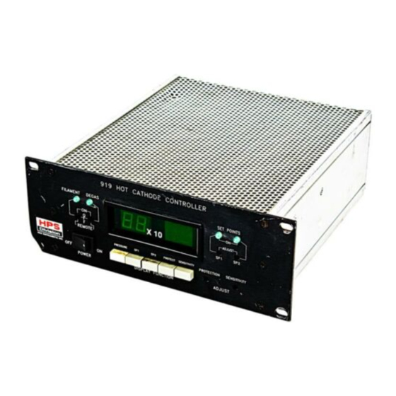
Page 28: Feature And Control Locations
Feature and Control Locations Controller Front Panel Rear Panel LED Digital Display LED Filament Indicator Protection Adjustment Potentiometer LED Degas Indicator Sensitivity Adjustment Potentiometer LED Set Point Indicators Female, 8-pin, High Power "D" type Set Point Adjustment Potentiometers Gauge Power Connector Power On-Off Rocker Switch Female, BNC Gauge Collector Filament On-Off-Remote Toggle Switch... - Page 29 Sensor Ø = 2¾" 3¼" Top View Side View Filament 1 Filament 2 Grid and Supports Ion Collector Sensor Vacuum Port and Flange Hot Cathode Ionization High Vacuum Senor System Artisan Technology Group - Quality Instrumentation ... Guaranteed | (888) 88-SOURCE | www.artisantg.com...
-
Page 30: Typical Applications For The Series 919 Hot Cathode System
Typical Applications for the Series 919 Hot Cathode System Measurement of high vacuum chamber pressures Control of high vacuum systems and process sequencing using a relay set point Sensing abnormal pressure and taking appropriate security measures using a relay set point Controlling system pressure using an automatic pressure control system Starting or stopping system processes... -
Page 31: About The Hps Products Series 919 Hot Cathode Ionization System
® About the HPS Products Series 919 Hot Cathode Ionization System The Series 919 Hot Cathode Ionization System, with its wide measurement range of 10 down to 10 Torr, is designed for versatility, simplicity, reliability, and value. A large, green LED display is easy to read in almost any lighting or angle. -
Page 32: Installing And Setting Up The Series 919 Hot Cathode System
Installing and Setting Up the Series 919 Hot Cathode System Hot Cathode Sensor Installation Location Locate the Sensor where it can measure chamber or manifold pressure. Installing the Sensor away from pumps and gas sources gives the most representative pressure values. Orientation The Series 919 Hot Cathode Sensor can be installed and operated in any position without compromising accuracy. - Page 33 The Controller operates with line frequencies of 50 or 60 Hz without any Select line voltage here adjustment necessary. It is configured at the factory to operate at either 100, 120, 220, or 240 VAC. To change a line voltage, Unplug the power cord from the Controller.
- Page 34 Rack with trim panel setup Half-Rack setup Add a face plate or secure another controller to the other half of the rack. Secure to the rack and to the other side of the splicing plate. To mount the Controller into a trim panel on the rack, as shown in the right figure above, Slip the Controller into the trim panel through the cutout.
- Page 35 AC Power Cord The Series 919 System includes a standard 120 VAC, 50/60 Hz power cord with a female IEC-320 connector. If the available power source or connection is different, use only a detachable cord set with conductors that have a cross-sectional area equal to or greater than 0.75 mm .
- Page 36 Pin 13 – Turn on the degas. The front panel Degas switch must be set to remote and either the front panel Filament switch is set to on or pin 10, remote filament-enable, is connected to a TTL low voltage or ground. If the filament turns off, degas will turn off automatically.
-
Page 37: Operating The Series 919 Hot Cathode System
Operating the Series 919 Hot Cathode System Be sure Controller power is off before plugging or unplugging a cable to the Sensor. Connecting or disconnecting cables while the Controller is on may damage the Sensor. Reading Pressure Turn the Power and Filament switches on and depress the Pressure Display Function push-button to measure and display pressure and to operate the set points. -
Page 38: Adjusting The Set Points
Output Voltage (VDC) Adjusting the Set Points The Series 919 Controller has two, independently adjustable set points that can be used throughout its operating range. LEDs indicate when the set points are active. When the power is turned off, the set points remain unchanged. -
Page 39: Adjusting The Filament Protection Limit
When an LED is on, the measured pressure is below the set point value, the normally open relay contact is closed, and the normally closed contact is open. When an LED is off, the measured pressure is above the set point value, the normally open relay contact is open, and the normally closed contact is closed. -
Page 40: Setting The Sensor Sensitivity
Setting the Sensor Sensitivity The ion current obtained at a given pressure and electron emission current depends upon the sensor design. The sensor sensitivity S is defined by the equation, x P) where, is ion current in amperes is electron emission current in amperes P is pressure in Torr. -
Page 41: Preparing For Sensor Bakeout
Degas the Sensor only when the pressure is below 5 x 10 Torr. To degas the Sensor, Turn both the Controller power and the Filament toggle on. Switch the Degas toggle on to begin degas. The LED above the switch will light up. Do not degas for more than 2 hours. -
Page 42: Using The Series 919 Hot Cathode System With Other Gases
Using the Series 919 Hot Cathode System with Other Gases A hot cathode ionization sensor measures pressure by the degree of ionization of a gas, so the pressure reading depends on the type of gas in the system. The Series 919 System is calibrated to read pressure for air or nitrogen. - Page 43 Depress the Sensitivity push-button on the Controller front panel, and adjust the Sensitivity potentiometer until the calculated value is displayed. Sensitivities Relative to Nitrogen Symbol Sensitivity (S 1.00 Argon 1.29 Carbon Dioxide 1.42 Deuterium 0.35 Helium 0.18 Hydrogen 0.46 Krypton 1.94 Neon 0.30...
-
Page 44: Maintaining The Series 919 Hot Cathode System
Maintaining the Series 919 Hot Cathode System Cleaning the Controller Front Panel The Series 919 Controller front panel is designed to resist most laboratory solvents. It can be cleaned with water or isopropyl alcohol. Do not use acetone on the front panel. Servicing the Controller The Series 919 Controller is designed to be maintenance-free under normal operation. -
Page 45: Testing The Sensor
Troubleshooting Chart Symptom Possible Cause Remedy No indication on display. 1. Verify power source and plug 1. Controller not plugged into proper it in to the correct one. power source. 2. Turn power on. 2. Power switch off. 3. Replace fuse. 3. -
Page 46: Accessories
Accessories Part # Accessory Connector Kit 100005087 Cable for the Low Power Nude Sensor, Molded Connectors 10 ft (3.0 m) 100006953 25 ft (7.6 m) 100006954 50 ft (15.2 m) 100006955 Custom 100006956 Sensor, Low Power Nude KF 40 Tungsten 100005987 2¾"... -
Page 47: Product Warranty
III. This warranty gives PURCHASER specific legal rights, and PURCHASER may also have other rights which vary from state to state. ® IV. For HPS products sold outside of the U.S., contact your MKS representative for warranty information and service. Warranty Performance ®... -
Page 48: Appendix A: How The Series 919 Hot Cathode System Works
Appendix A: How the Series 919 Hot Cathode System Works Theory of a Hot Cathode Ionization Sensor Hot cathode ionization sensors use thermionic electrons, electrons emitted from a hot filament, to create ions in a defined volume. In their passage from the cathode through the gas volume, the electrons collide with gas atoms or molecules to form ions. -
Page 49: Notes
Notes Hot Cathode Ionization High Vacuum Senor System Artisan Technology Group - Quality Instrumentation ... Guaranteed | (888) 88-SOURCE | www.artisantg.com... - Page 50 The Series 919 Hot Cathode System Design Overview Circuit Description This section is intended to give the reader an overview of the internal work- ings of the Series 919 Controller. This manual does not provide sufficient detail to allow component level troubleshooting of the instrument. Refer to the figure below, the system block diagram, while reading this section.
- Page 51 Electrometer The electrometer is a logarithmic current to voltage converter used to measure the sensor ion current. This electrometer has a dynamic range wide enough to cover the entire pressure range with no electronic range changing. Signal Processing Taking the output from the log electrometer, inverting it, and summing it with a reference voltage generates the logarithmic output.
- Page 52 Artisan Technology Group - Quality Instrumentation ... Guaranteed | (888) 88-SOURCE | www.artisantg.com...
- Page 53 Artisan Technology Group - Quality Instrumentation ... Guaranteed | (888) 88-SOURCE | www.artisantg.com...
Need help?
Do you have a question about the HPS 919 Series and is the answer not in the manual?
Questions and answers