Table of Contents
Advertisement
Advertisement
Table of Contents

Subscribe to Our Youtube Channel
Related Manuals for Abit LG95C


Summary of Contents for Abit LG95C
- Page 1 LG-95Z V2.0 LG-95C Motherboard Intel Socket 775 Installation Guide...
- Page 2 If you do not properly set the motherboard settings, causing the motherboard to malfunction or fail, we cannot guarantee any responsibility. The Following Information is Only for EU-member States: Directive 2002/96/EC on Waste Electrical and Electronic Equipment (WEEE): The use of the symbol indicates that this product may not be treated as household waste.
-
Page 3: Table Of Contents
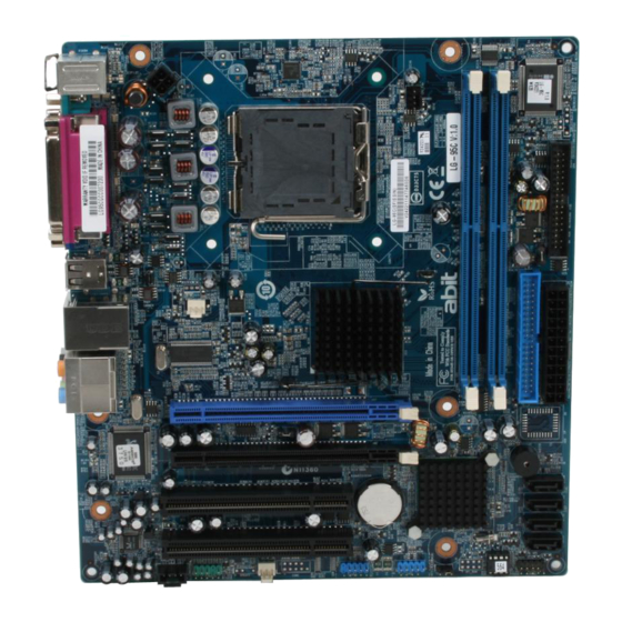
Contents 1. Hardware Setup ... 1 1.1 Specifications ...1 1.2 Choosing a Computer Chassis...2 1.3 Installing Motherboard...2 1.4 Checking Jumper Settings ...3 1.4.1 CMOS Memory Clearing Header and Backup Battery ...3 1.5 Connecting Chassis Components ...4 1.5.1 ATX Power Connectors ...4 1.5.2 Front Panel Switches and Indicators Headers...5... - Page 4 LG-95Z V2.0 Layout LG-95C Layout The motherboard and its component layouts illustrated in the ※ following chapter of this manual were mainly based on model “LG-95Z V2.0”, unless specifically stated. LG-95Z V2.0/LG-95C...
-
Page 5: Hardware Setup
1. Hardware Setup 1.1 Specifications • LGA775 socket for Intel Core 2 Duo / Pentium Dual-Core / Pentium D / Pentium 4 / Celeron D processor with 800MHz FSB • Supports Intel Hyper-Threading Technology Chipset • LG-95Z V2.0: Intel 945GZ / ICH7 •... -
Page 6: Choosing A Computer Chassis
Plug in the AC power cord only after you have carefully checked everything. To install this motherboard: 1. Locate all the screw holes on the motherboard and the chassis base. 2. Place all the studs or spacers needed on the chassis base and have them tightened. -
Page 7: Checking Jumper Settings
1.4 Checking Jumper Settings For a 2-pin jumper, plug the jumper cap on both pins will make it CLOSE (SHORT). Remove the jumper cap, or plug it on either pin (reserved for future use) will leave it at OPEN position. SHORT OPEN For a 3-pin jumper, pin 1~2 or pin 2~3 can be shorted by plugging the... -
Page 8: Connecting Chassis Components
or “CMOS checksum error” displays on monitor, this backup battery is no longer functional and has to be renewed. To renew the backup battery: 1. Power off the system and disconnect with AC power source. 2. Remove the exhausted battery. 3. -
Page 9: Front Panel Switches And Indicators Headers
1.5.2 Front Panel Switches and Indicators Headers This header is used for connecting switches and LED indicators on the chassis front panel. Watch the power LED pin position and orientation. The mark “+” align to the pin in the figure below stands for positive polarity for the LED connection. -
Page 10: Installing Hardware
1.6 Installing Hardware DO NOT scratch the motherboard when installing hardware. An ※ accidental scratch of a tiny surface-mount component may seriously damage the motherboard. In order to protect the contact pins, please pay attention to these ※ notices: 1. A maximum 20 cycles of CPU installation is recommended. - Page 11 8. Place the heatsink and fan assembly onto the socket. Align the four fasteners toward the four mounting holes on the motherboard. 9. Press each of the four fasteners down into the mounting holes. Rotate the fastener clock-wise to lock the heatsink and fan assembly into position.
-
Page 12: Ddr2 Memory Slots
1.6.2 DDR2 Memory Slots • To reach the optimum performance in dual-channel configurations, install identical DDR2 DIMM pairs for each channel. • Install DIMMs with the same CAS latency. To reach the optimum compatibility, obtain memory modules from the same vendor. Usually there is no hardware or BIOS setup required after adding or ※... -
Page 13: Connecting Peripheral Devices
2. Attach the SATA power cable to the SATA device and connect the other end from the power supply. The motherboard in this photo is served for DEMO only, and may not ※ be the same type or model as the one described in this manual. -
Page 14: Additional Usb 2.0 Port Headers
1.7.3 Additional USB 2.0 Port Headers Each header supports 2x additional USB 2.0 ports by connecting bracket or cable to the rear I/O panel or the front-mounted USB ports of your chassis. Pin Assignment Data0 - Data0 + Ground Make sure the connecting cable bears the same pin assignment. ※... -
Page 15: Front Panel Audio Connection Header
1.7.5 Front Panel Audio Connection Header This header provides the connection to audio connector at front panel. Signal Name Function AUD_MIC Front Panel Microphone input signal AUD_GND Ground used by Analog Audio Circuits AUD_MIC_BIAS Microphone Power AUD_VCC Filtered +5V used by Analog Audio Circuits AUD_F_R Right Channel audio signal to Front Panel Right Channel Audio signal to Return... -
Page 16: Lg-95Z V2.0/Lg-95C
1.8 Connecting Rear Panel I/O Devices The rear I/O part of this motherboard provides the following I/O ports: • Mouse: Connects to PS/2 mouse. • Keyboard: Connects to PS/2 keyboard. • LPT1: Connects to printer or other devices that support this communication protocol. -
Page 17: Bios Setup
2. BIOS Setup This motherboard provides a programmable EEPROM so that you can update the BIOS utility. The BIOS (Basic Input/Output System) is a program that deals with the basic level of communication between processor and peripherals. Use the BIOS Setup program only when installing motherboard, reconfiguring system, or prompted to “Run... -
Page 18: Driver & Utility
3. Driver & Utility The “Driver & Utility CD” that came packed with this motherboard contains drivers, utilities and software applications required for its basic and advanced features. Place the “Driver & Utility CD” into the CD-ROM drive in your system. -
Page 19: Appendix
4. Appendix 4.1 規格(繁體中文) 處理器 • 支援具備 800MHz 前端匯流排的 Intel Core 2 Duo / Pentium Dual-Core / Pentium D / Pentium 4 / Celeron D 處理器 • 支援 Intel Hyper-Threading 技術 晶片組 • LG-95Z V2.0:Intel 945GZ / ICH7 • LG-95C:Intel 945GC / ICH7 記憶體... -
Page 20: 规格(简体中文
4.2 规格(简体中文) 处理器 • 支持具备 800MHz 前端总线的 Intel Core 2 Duo / Pentium Dual-Core / Pentium D / Pentium 4 / Celeron D 处理器 • 支持 Intel 超线程技术 芯片组 • LG-95Z V2.0:Intel 945GZ / ICH7 • LG-95C:Intel 945GC / ICH7 内存... -
Page 21: Troubleshooting (How To Get Technical Support?)
4.3 Troubleshooting (How to Get Technical Support?) 4.3.1 Q & A Do I need to clear the CMOS before I use a new motherboard to assemble my new computer system? Yes, we highly recommend that you clear the CMOS before installing a new motherboard. -
Page 22: Technical Support Form
See the blank Technical Support Form, or visit our website to fill in the form on line (http://www.abit.com.tw/page/en/contact/technical.php). Is the motherboard dead? Do I need to return it to where I bought from or go through an RMA process? After you have gone through the troubleshooting procedures, yet the problem still exists, or you find an evident damage on the motherboard, please contact our RMA center. -
Page 23: Contact Information
Website: http://www.abit-usa.com Latin America: r aymond@abit-usa.com RMA Center: http://rma.abit-usa.com UK, Ireland Universal ABIT UK Co. Ltd. Unit 3, 24-26 Boulton Road, Stevenage, Herts SG1 4QX, United Kingdom Tel: +44-1438-228888 Fax: +44-1438-226333 For technical support and RMA return: Tel: +44-1438-362088 technical@abitcomputer.co.uk returns@abitcomputer.co.uk... - Page 24 P/N: 4310-0000-86 Rev. 3.00...
Need help?
Do you have a question about the LG95C and is the answer not in the manual?
Questions and answers